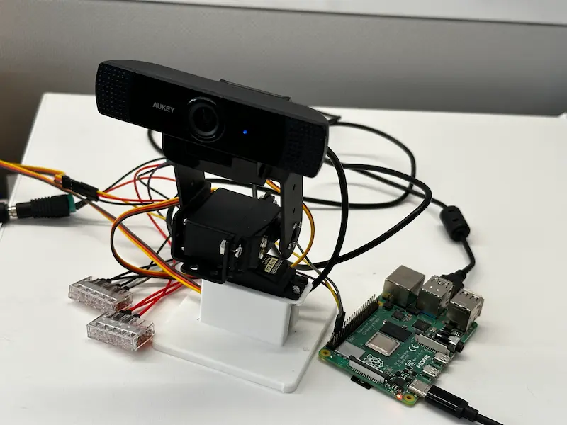
In this tutorial, we'll show you how to build your own pan-tilt camera that can track any object using computer vision. If you've ever been curious how those smart webcams from Insta360 or gimbals from DJI work, you'll learn those fundamentals while building this project.
What You'll Build
- An object tracking camera with servos and computer vision
Prerequisites
- A computer with MacOS, Windows, or Linux to flash your Raspberry Pi and configure the device's components using the Viam app
- Hardware and supplies requirements
- 1 - Raspberry Pi 4
- 1 - microSD card to use with your Pi
- 1 - power supply for your Pi
- 1 - USB webcam with a screw mount
- 2 - TowerPro SG-5010 servos
- 1 - pan-tilt servo mount brackets
- 1 - 5V barrel jack power supply with DC terminal header adapter
- 1 - Assortment of WAGO lever nuts
- 1 - Assortment of jumper wires
- 1 - Phillips screwdriver
- 1 - 3D printed base (optional)
What You'll Learn
- How to configure and test a device's components using Viam
- How to use modules from the Viam registry
- How to deploy an ML model for computer vision
- How to use a vision service for object detection
- How to use custom modules for automated behavior
What You'll Need
- All the hardware components listed in prerequisites.
- Sign up for a free Viam account, and then sign in to the Viam app
Watch the Video
See a demonstration of the AI tracking camera in action:
The Raspberry Pi boots from a storage device, such as a USB flash drive or microSD card. You need to install Raspberry Pi OS on that storage device that you will use with your Pi. For more details about alternative methods of setting up your Raspberry Pi, refer to the Viam docs.
Install Raspberry Pi OS
- Connect the storage device to your computer.
- Download the Raspberry Pi Imager and launch it.
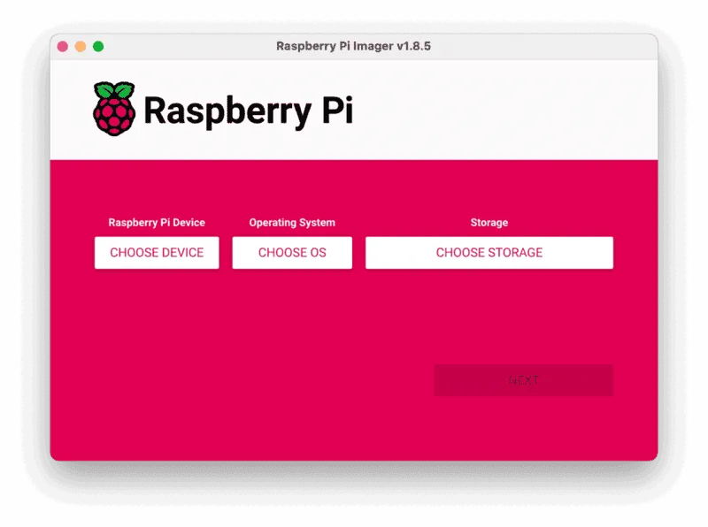
- Click CHOOSE DEVICE. Select your model of Pi, which is Raspberry Pi 4.
- Click CHOOSE OS. Select Raspberry Pi OS (64-bit) from the menu.
- Click CHOOSE STORAGE. From the list of devices, select the storage device you intend to use in your Raspberry Pi.
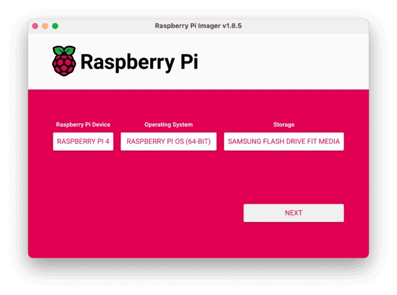
- Configure your Raspberry Pi for remote access. Click Next. When prompted to apply OS customization settings, select EDIT SETTINGS.
- Check Set hostname and enter the name you would like to access the Pi by in that field, for example,
test. - Select the checkbox for Set username and password and set a username (for example, your first name) that you will use to log into the Pi. If you skip this step, the default username will be
pi(not recommended for security reasons). And specify a password. - Connect your Pi to Wi-Fi so that you can run
viam-serverwirelessly. Check Configure wireless LAN and enter your wireless network credentials. SSID (short for Service Set Identifier) is your Wi-Fi network name, and password is the network password. Change the sectionWireless LAN countryto where your router is currently being operated.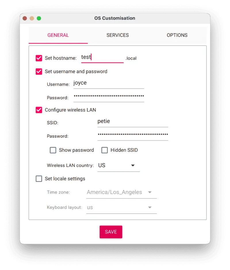
- Select the SERVICES tab, check Enable SSH, and select Use password authentication.
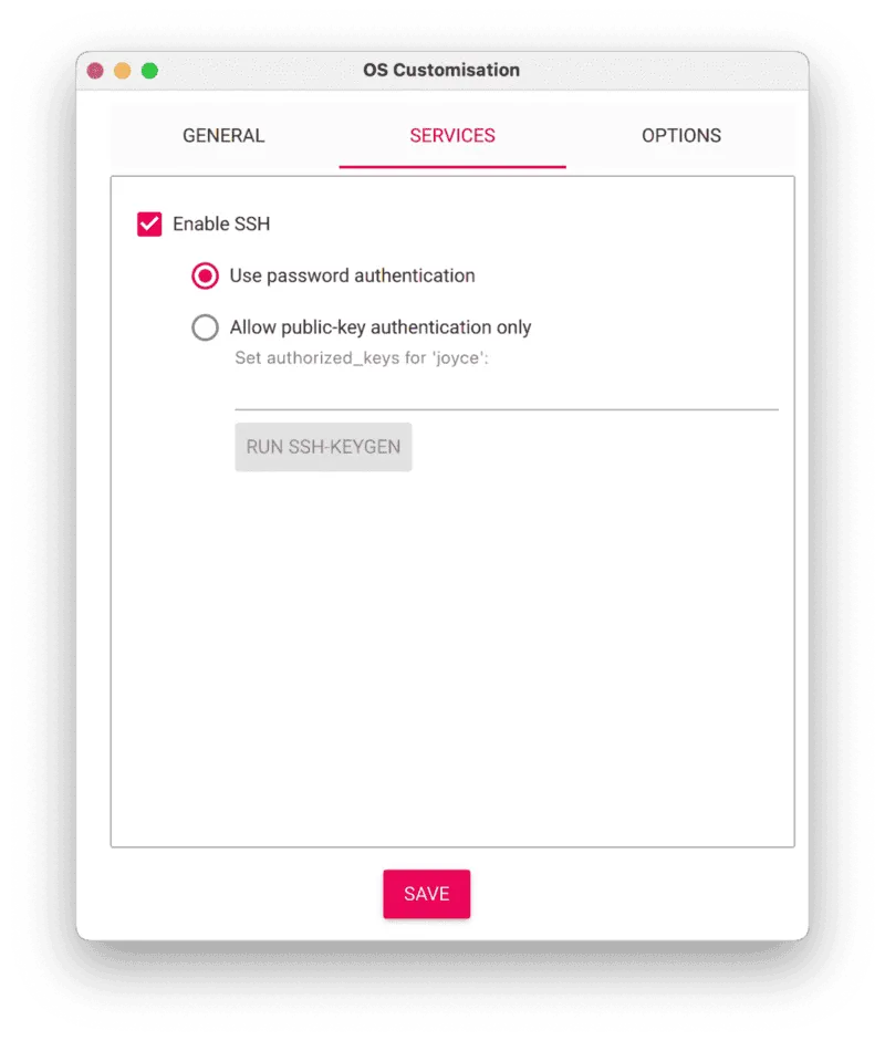
- Save your updates, and confirm
YESto apply OS customization settings. ConfirmYESto erase data on your storage device. You may also be prompted by your operating system to enter an administrator password. After granting permissions to the Imager, it will begin writing and then verifying the Linux installation to your storage device. - Remove the storage device from your computer when the installation is complete.
Connect with SSH
- Place the storage device into your Raspberry Pi and boot the Pi by plugging it in to an outlet. A red LED will turn on to indicate that the Pi is connected to power.
- Once the Pi is started, connect to it with SSH. From a command line terminal window, enter the following command. The text in <> should be replaced (including the < and > symbols themselves) with the user and hostname you configured when you set up your Pi.
ssh <USERNAME>@<HOSTNAME>.local - If you are prompted "Are you sure you want to continue connecting?", type "yes" and hit enter. Then, enter the password for your username. You should be greeted by a login message and a command prompt.
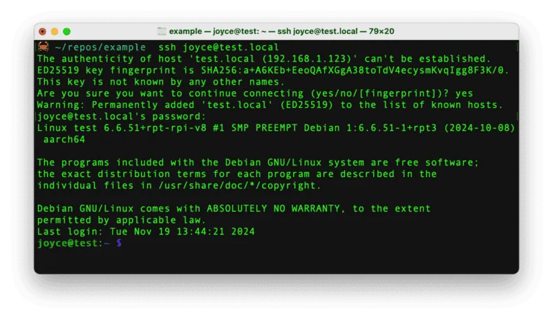
- Update your Raspberry Pi to ensure all the latest packages are installed
sudo apt update
sudo apt upgrade
Before we get to wiring up the components, let's assemble the servo brackets and mount the webcam.
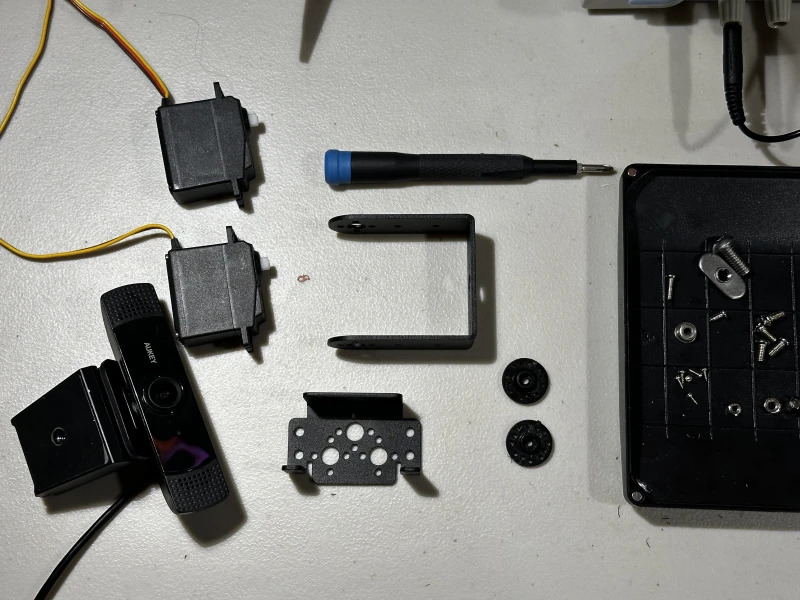
- You should have the following parts ready for assembly
- 2 servos
- webcam
- Philips Head screwdriver
- top servo bracket (U-shaped)
- bottom servo bracket
- 2 round servo horns
- assortment of screws and nuts (and one bearing) from the bracket kit
- Grab one of the servos, round servo horns, the horn set screw, and your screwdriver.
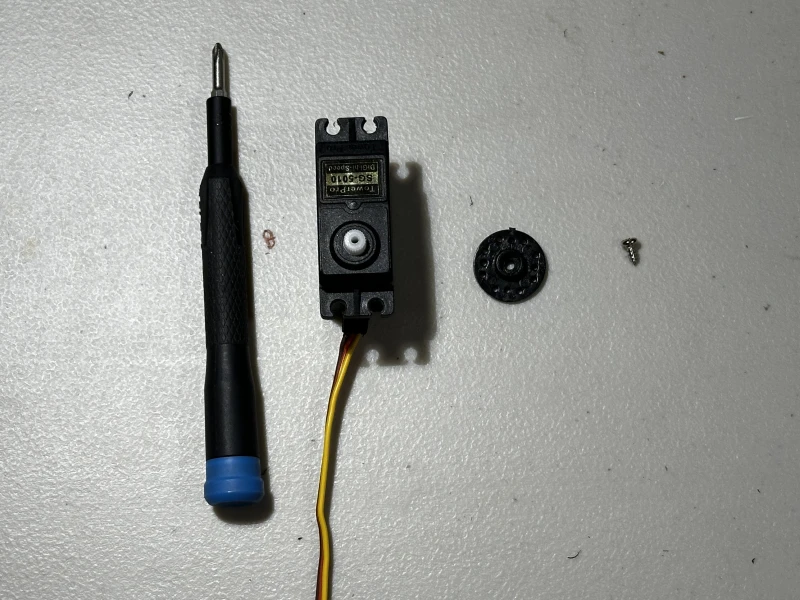
- Push the servo horn onto the head of the servo.
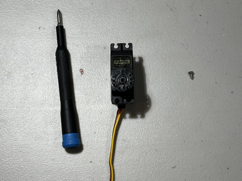
- Screw the set screw into the servo to secure the horn in place.
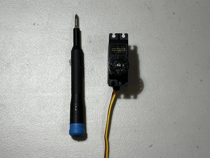
- Grab the bottom bracket and two small servo horn screws along with the servo you've been working on.
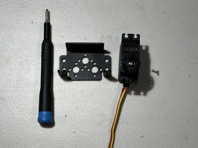
- Place the bracket on top of the servo horn, aligning the far right holes to secure the bracket onto the horn with the small screws.
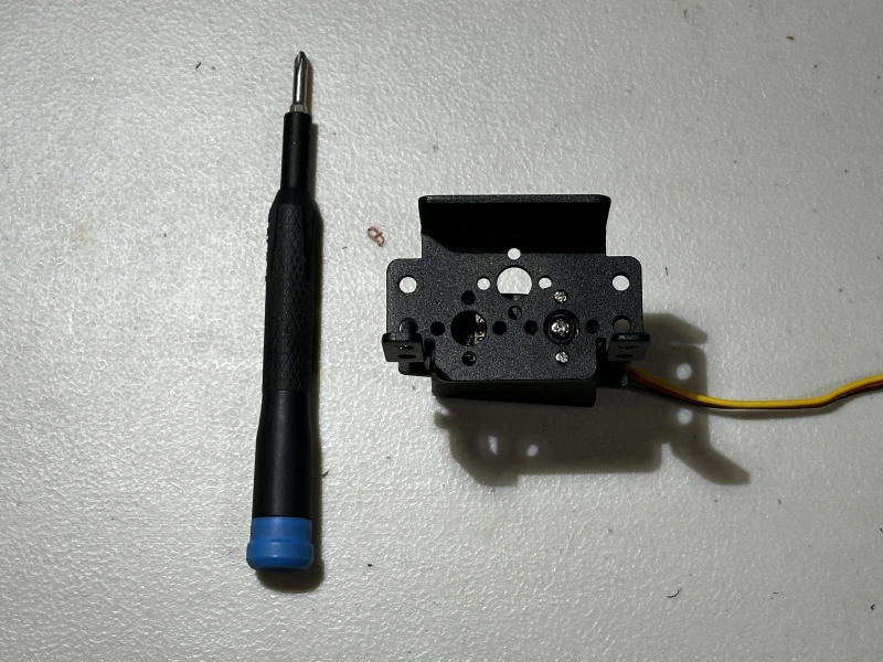
- Grab the top bracket, a servo horn, a round bearing, the longest screw with matching nut, two of the thicker screws with matching nuts, the second servo along with the parts you've been working on.
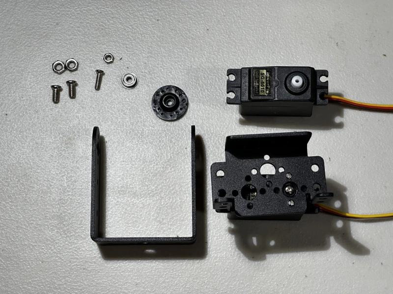
- Push the servo horn onto the head of the second servo.
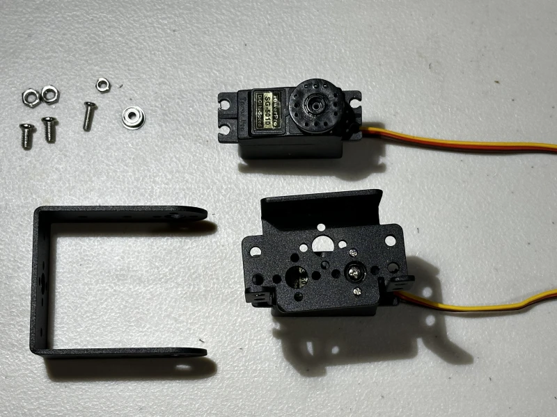
- Set the long screw into the center hole of the bottom bracket perpendicular to the bottom servo.
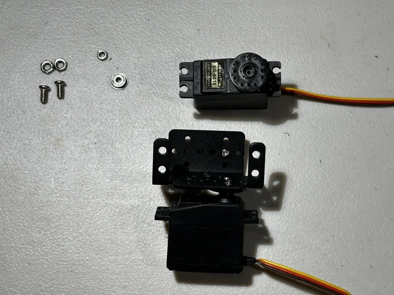
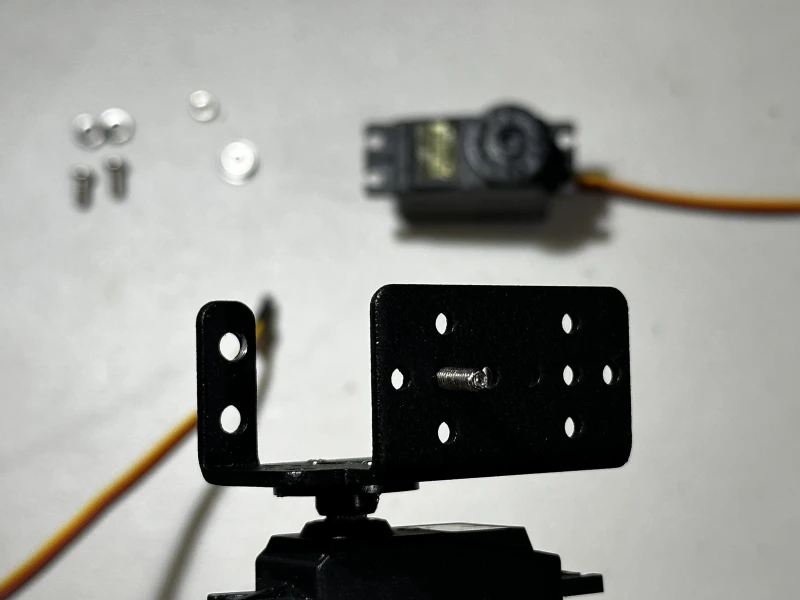
- Place the top servo onto the bottom bracket.
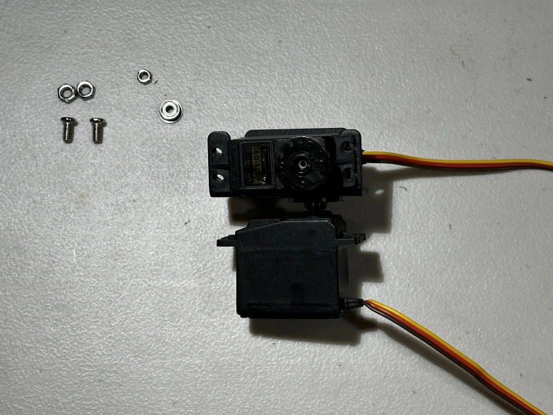
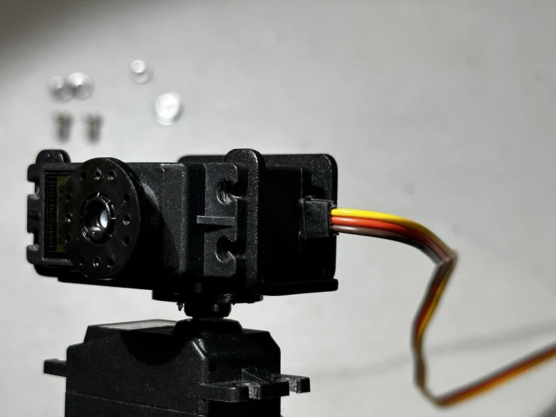
- Secure the top servo in place with the thicker screws in the bottom bracket, using the nuts to tighten by hand.
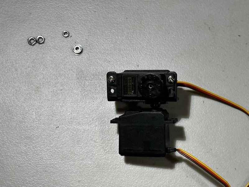
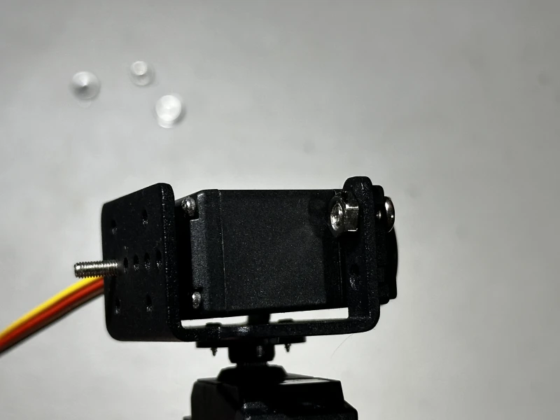
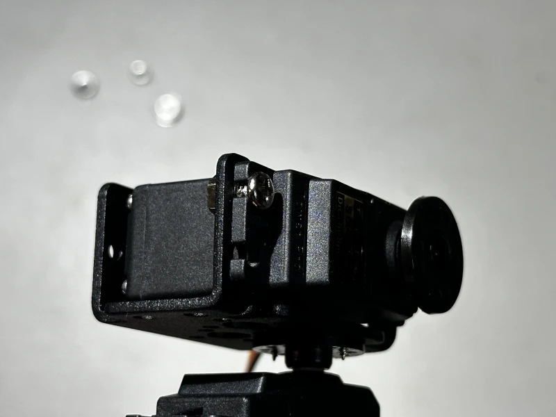
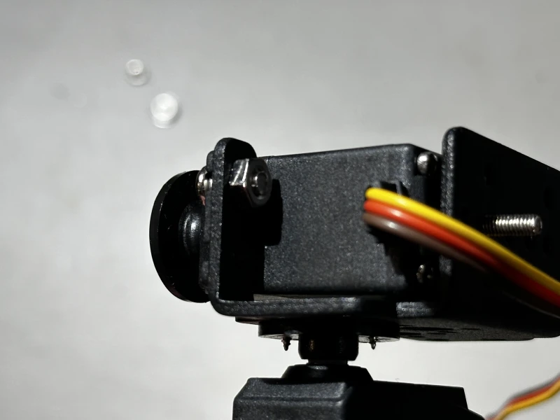
- Grab four small servo horn screws along with the current parts.
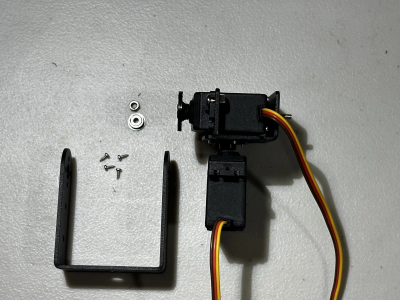
- Place the bearing on the long screw behind the top servo.
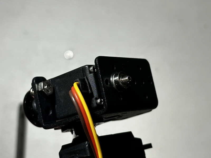
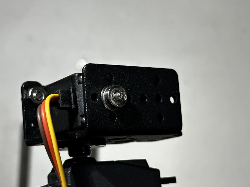
- Fit the top bracket legs around the bearing and top servo horn.
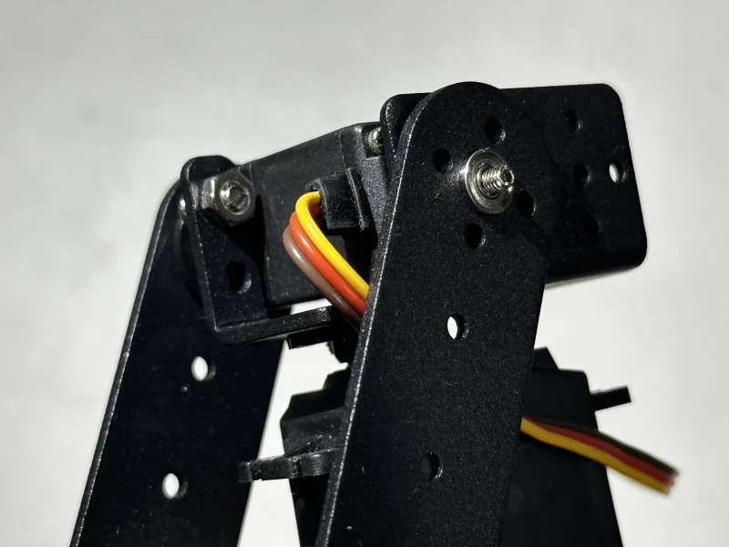
- Align the small holes of the leg over the servo horn with four holes to secure it in place with screws.
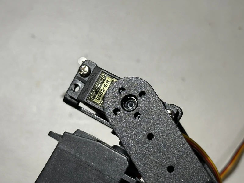
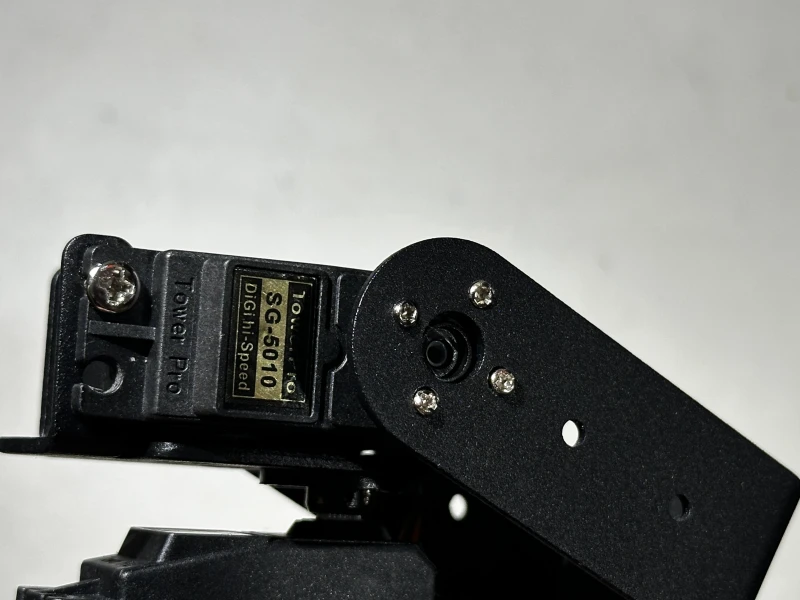
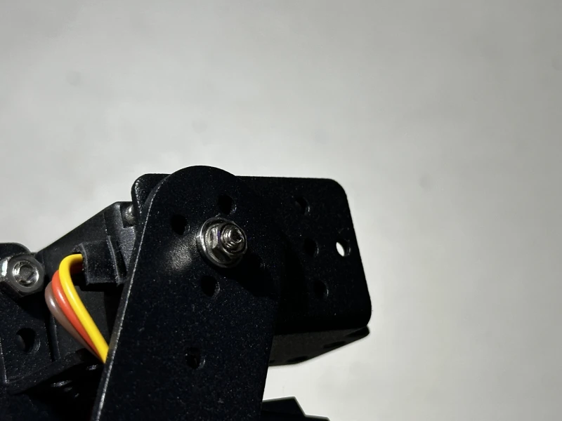
- Secure the bearing in the place with the matching nut.
- Grab the webcam, mount screw, and washer along with the currently assembled parts.
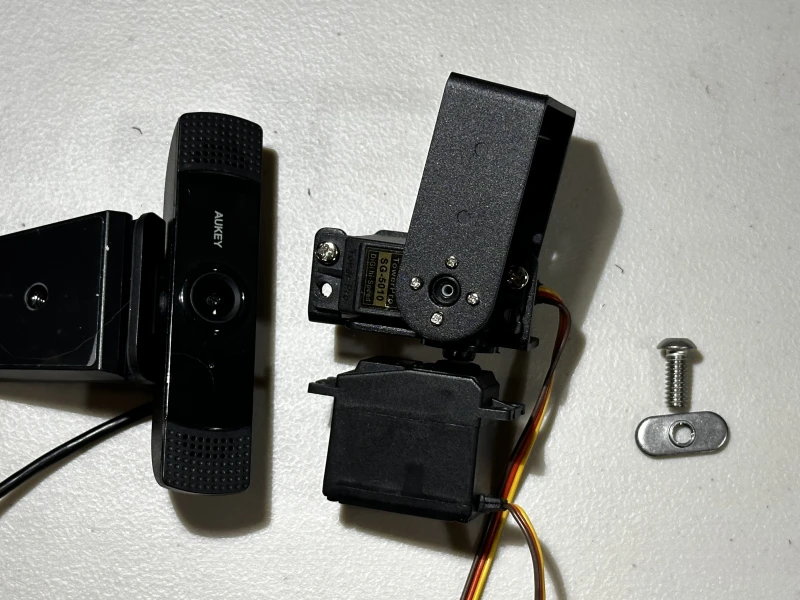
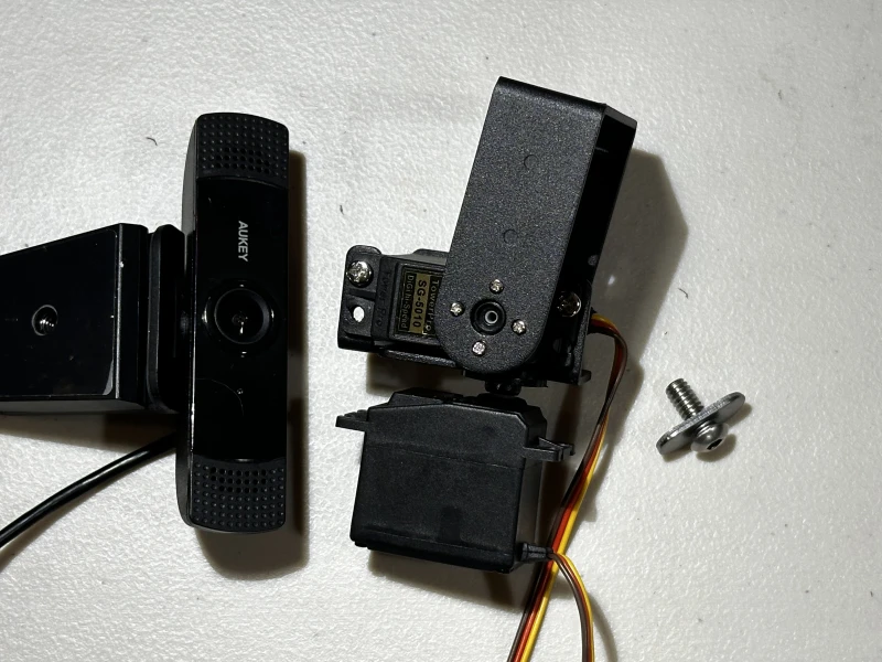
- Set the mount screw into the washer with the flat part facing down.
- Push the mount screw through the bottom of the center hole on the top bracket, then turn the webcam onto the screw, tighten by hand in the expected direction.
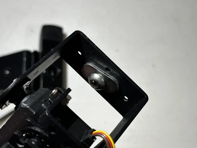
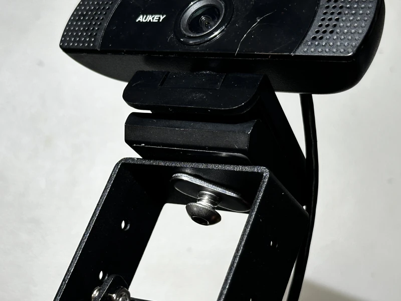
Nice work! With the servo bracket mount complete, you can wire the components to the power supply and Raspberry Pi.
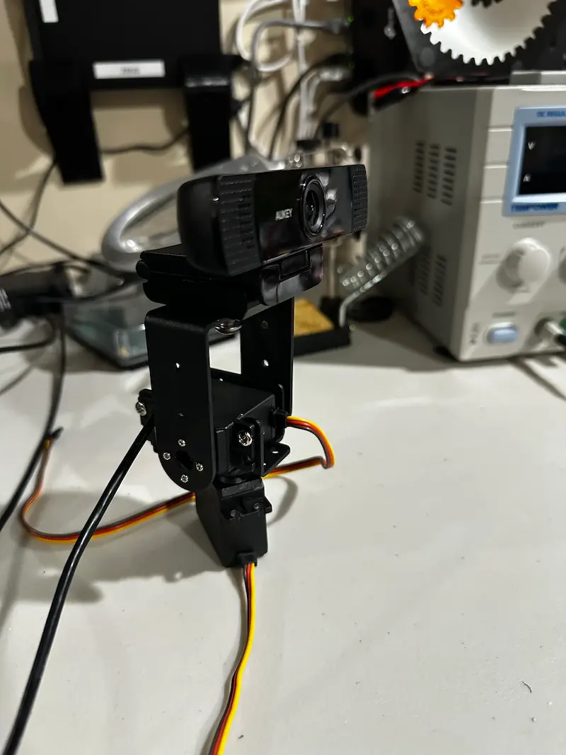
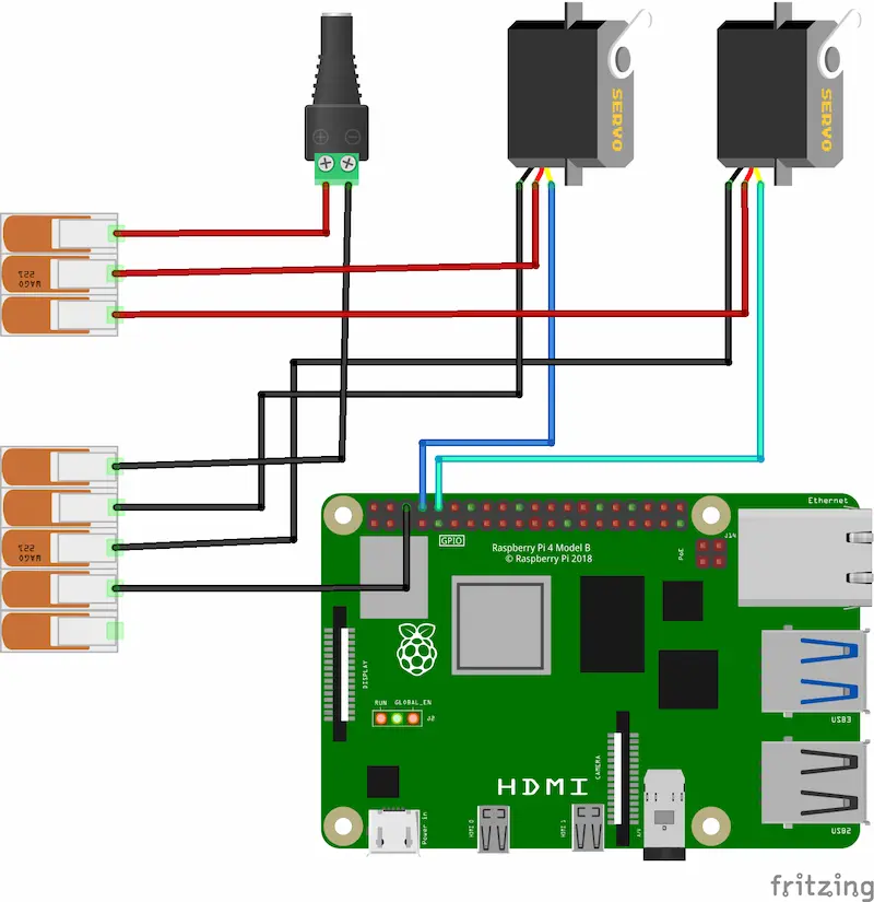
- Use the above wiring diagram to connect the hardware peripherals and power together. The power and ground connections from the barrel jack power supply with the DC screw-terminal adapter will be shared among the servos and Raspberry Pi using the WAGO lever nuts.The 5-port WAGO bridging all the ground connections will be known as "Common Ground". The 3-port WAGO bridging the servos and DC power connections will be known as "Common Power".
Board to Pan Servo:
Jumper wires are required to connect the servo wires to the Raspberry Pi. The pan servo is the first servo assembled, on the bottom.Raspberry Pi
Servo
Pin 8 (GPIO 14)
Data wire (yellow)
Board to Tilt Servo:
Jumper wires are required to connect the servo wires to the Raspberry Pi. The tilt servo is the second servo assembled, on the top holding the U-shaped bracket.Raspberry Pi
Servo
Pin 10 (GPIO 15)
Data wire (yellow)
Board to Power:
Raspberry Pi
Power
Pin 6 (Ground)
Common Ground
Servo to Power:
Jumper wires are required to connect the servo wires to each WAGO.
repeat for each servoServo
Power
Power wire (red)
Common Power
Ground wire (brown)
Common Ground
- Connect the webcam USB plug to to any of the Raspberry Pi's USB-A ports.

Well done! 👏
Now you can plug in the DC power supply for the servos.
In the next section, you'll configure your device in the Viam app and start controlling your hardware!
Configure your machine
- In the Viam app under the LOCATIONS tab, create a machine by typing in a name and clicking Add machine.

- Click View setup instructions.
- To install
viam-serveron the Raspberry Pi device that you want to use, select theLinux / Aarch64platform for the Raspberry Pi, and leave your installation method asviam-agent.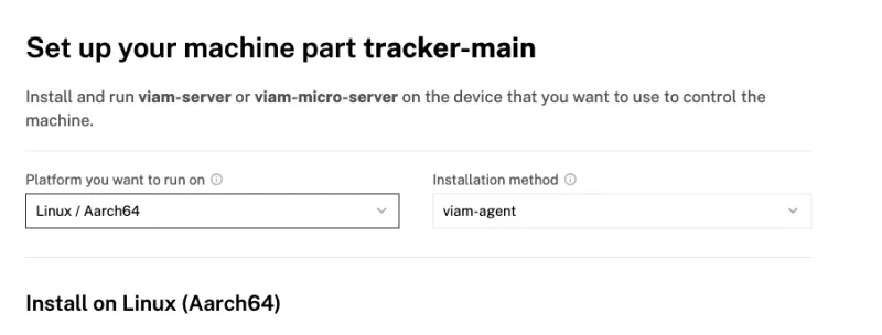
- Use the
viam-agentto download and installviam-serveron your Raspberry Pi. Follow the instructions to run the command provided in the setup instructions from the SSH prompt of your Raspberry Pi.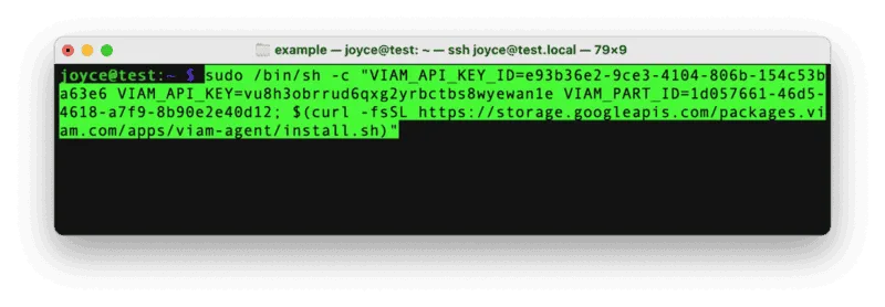
- The setup page will indicate when the machine is successfully connected.

Configure your Raspberry Pi board
To access the GPIO pins, let's add our Raspberry Pi board to our machine in the Viam app.
- In the Viam app, find the CONFIGURE tab.
- Click the + icon in the left-hand menu and select Component.
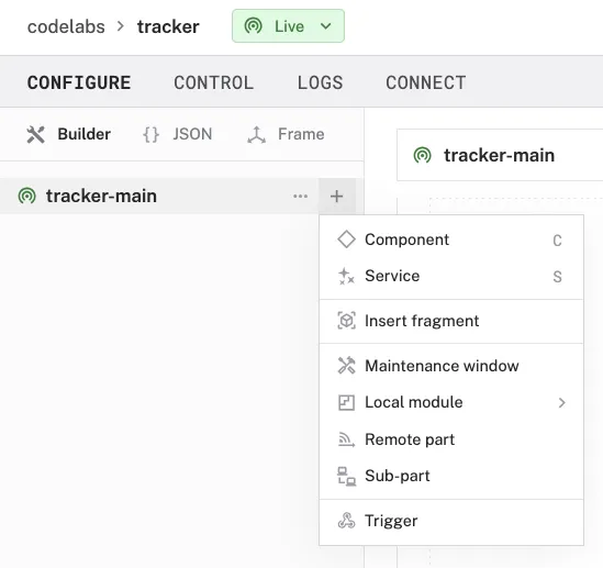
- Select
board, and find theraspberry-pi:rpi4module. This adds the module for working with the Raspberry Pi 4's GPIO pins. Leave the default nameboard-1for now.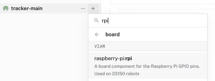
- Notice adding this module adds the board hardware component called
board-1. The collapsible card on the right corresponds to the part listed in the left sidebar. - Click Save in the top right to save and apply your configuration changes.
Configure your webcam
- In the Viam app under the CONFIGURE tab, click the + icon in the left-hand menu and select Component.
- Select
camera, and find thewebcammodule. This adds the module for working with a USB webcam. Leave the default namecamera-1for now. - Notice adding this component adds the webcam hardware component called
camera-1. From the Configure section of the panel, switch to the JSON configuration mode using the{}icon in the top-right:
- In this mode, configure your component with the following JSON in the CONFIGURE field. This will tell the component to look for the default camera connected to the device, which will be the USB webcam.
{
  "video_path": ""
}
- Click Save in the top right. This may take a moment to apply your configuration changes.
- At the bottom of the
camera-1panel, expand the TEST section to ensure you have configured the camera properly and see a video feed.
Configure your pan servo
- In the Viam app, find the CONFIGURE tab.
- Click the + icon in the left-hand menu and select Component.
- Select servo, and find the
raspberry-pi:rpi-servomodule. This adds the module for controlling a servo with a Raspberry Pi's GPIO pins. Set the name topanto help indicate the responsibility of this servo.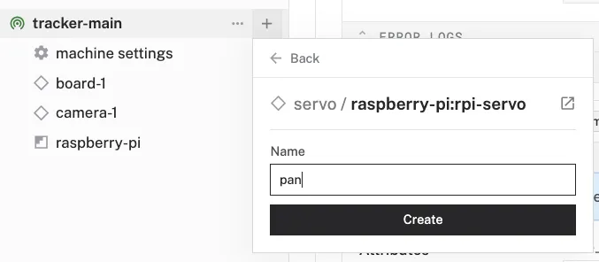
- Notice adding this module adds the servo hardware component called
pan. The collapsible card on the right corresponds to the part listed in the left sidebar. - In the new
panpanel, configure your component with the following JSON in the CONFIGURE field. This tells your servo component to use a specific pin on a specific board (calledboard-1in the Viam app).{ "board": "board-1", "pin": "8" }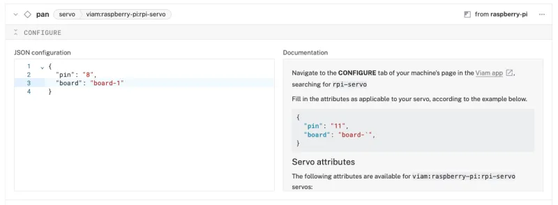
- Click Save in the top right to save and apply your configuration changes.
- At the bottom of the
panpanel, expand the TEST section to ensure you have configured the servo correctly. You should see the servo move the camera mount left and right using the Quick move controls.
Configure your tilt servo
- In the Viam app, find the CONFIGURE tab.
- Click on the ... in the top-right corner of the
panservo panel to reveal an action menu. Select Duplicate to create a copy of the component for the tilt servo in the configuration.
- A new component card will appear with the name of the
panservo component plus "-copy". Click on the name and rename it totilt.
- In the new
tiltpanel, configure your component with the following JSON in the CONFIGURE field. This tells your servo component to use a specific pin on a specific board (calledboard-1in the Viam app).{ "board": "board-1", "pin": "10" }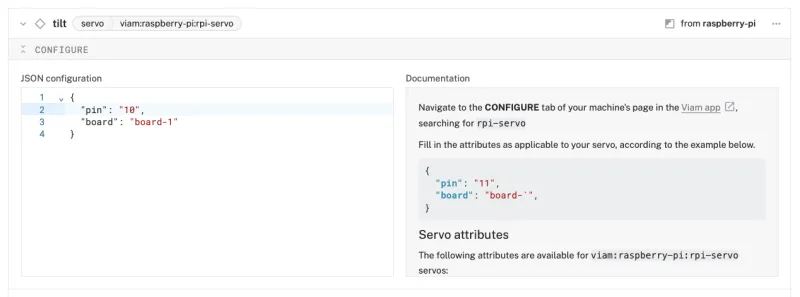
- Click Save in the top right to save and apply your configuration changes.
- At the bottom of the
tiltpanel, expand the TEST section to ensure you have configured the servo correctly. You should see the servo move the camera mount up and down using the Quick move controls.
Configure your base
- In the Viam app under the CONFIGURE tab, click the + icon in the left-hand menu and select Component.
- Select
base, and find thepan-tilt-camera:base-controlmodule. This adds the module for sending directions to a pair of pan-tilt servos from a single component. Leave the default namebase-1for now.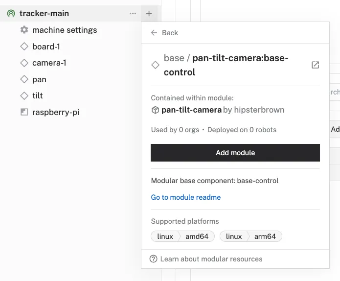
- In the new
base-1panel, configure your component with the following JSON in the CONFIGURE field. This tells your base component which servos to use for the pan and tilt functionalities.{ "pan": "pan", "tilt": "tilt" }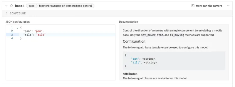
- Click Save in the top right. This may take a moment to apply your configuration changes.
- At the bottom of the
base-1panel, expand the TEST section to ensure you have configured the base properly. After toggling the keyboard control under the Quick move section, you should see the appropriate servo move when using your keyboar's arrow keys or WASD. Remember to toggle off the keyboard control when you're ready to use the keyboard regularly again.
With your hardware components confirmed working, now we will provide the intelligence to enable real-time object tracking!
Add an ML model service
- In the Viam app, click the + icon in the left-hand menu and select Service, and then
ML model. - Search for a module called
TFLite CPU. Then click Add module, and Create a new ML Model service calledmlmodel-1. This provides the ability to run Tensorflow Lite, a.k.a LiteRT, models on the machine.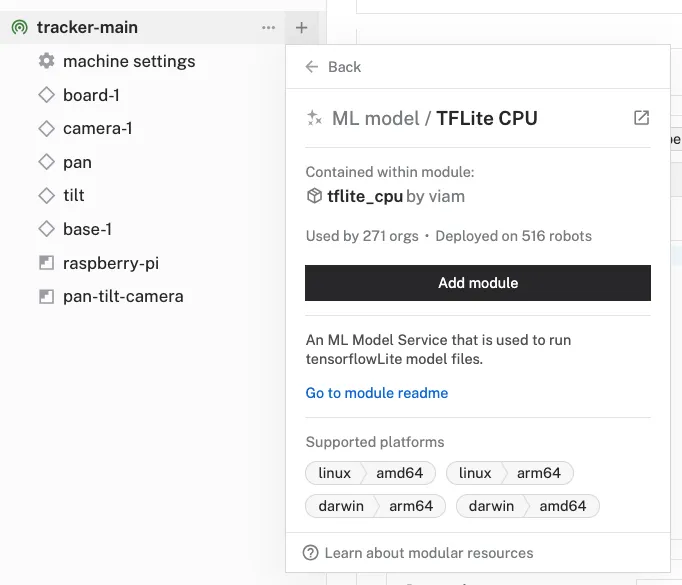
- Notice this creates two new items in the left sidebar. The first is your new ML Model service called
mlmodel-1, and the second is thetflite_cpumodule from the Registry. - In the
mlmodel-1panel, click "Select model" in the Model section, search for "EfficientDet-COCO" under the Registry tab, and select the model from the list.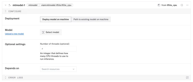
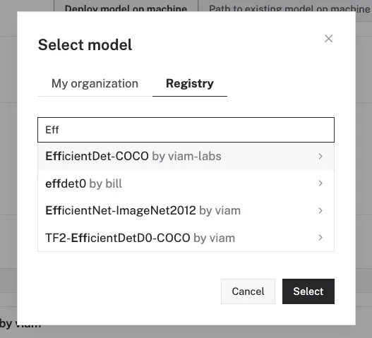
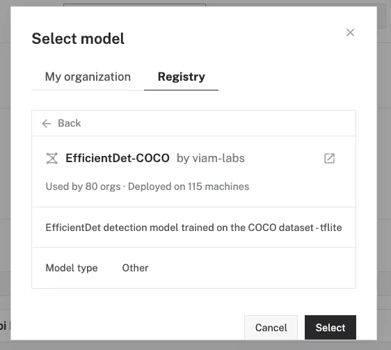
- Click Save in the top right to save and apply your configuration changes.
Add a vision service
- In the Viam app, click the + icon in the left-hand menu and select Service, and then
vision. - Search for a module called
mlmodel. Then click Add module, and Create a new Vision service calledvision-1.
- Notice adding this service adds the vision service called
vision-1. From the ML Model section of the panel, selectmlmodel-1.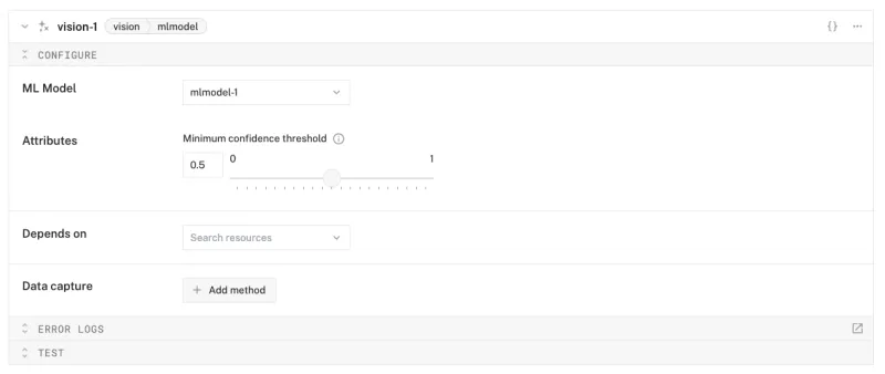
- Save your changes in the top right and wait a few moments for the configuration changes to take effect.
- At the bottom of the
vision-1panel, expand the TEST section to ensure you have configured the service properly and can see the labels detected by the model with bounding boxes around each detected object.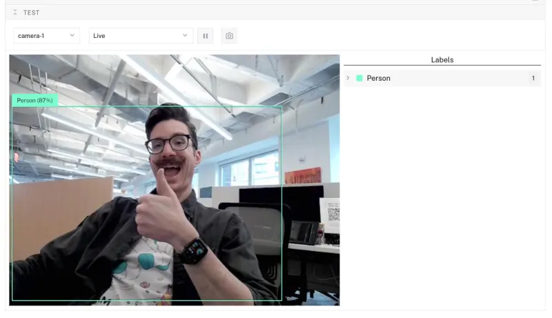
Add the tracker service
- In the Viam app, click the + icon in the left-hand menu and select Service, and then
generic. - Search for a module called
pan-tilt-camera:tracker. Then click Add module, and Create a new tracker service calledtracking.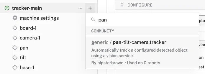
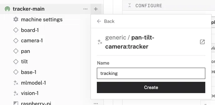
- Notice adding this service adds the generic service called
tracking. - In the new
trackingpanel, configure the service by adding the following attributes in the CONFIGURE field. This tells the tracker service to use specific base and camera components along with a specific vision service to look for a certain object label:{ "base_name": "base-1", "camera_name": "camera-1", "vision_name": "vision-1", "auto_start": true, "object_label": "Person" }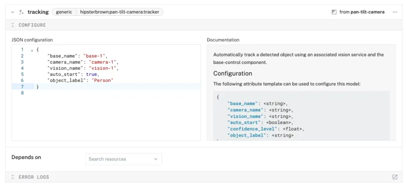
- Save your changes in the top right and wait a few moments for the configuration changes to take effect.
- Test out the service by looking at the TEST panel of the vision service and move around in front of the camera. You will see it respond to your movements to keep you in the center of the frame. Experiment with changing the "object_label" field to any of the detected labels displayed by the vision service, such as "Cellphone" or another one of the many objects detected by this model, and use that object to guide the camera movement.
Congratulations! Now you have an automated camera system that can track objects in real time using off-the-shelf components! While this project looks just a bit different from those commercial tracking webcams, it's given you a taste of key hardware hacking concepts - from servo control to computer vision to hardware automation.
What You Learned
- How to configure and test a device's components using Viam
- How to use modules from the Viam registry
- How to deploy an ML model for computer vision
- How to use a vision service for object detection
- How to use custom modules for automated behavior
Building advanced scenarios with Viam and the AI tracking camera
At this point, you have configured and tested your machine to track objects. Consider adding features like:
- use, or train, a model to detect faces for more precise people tracking.
- add voice control using a speech module
- build a custom web or mobile application to monitor and control using the Viam SDKs
- add tracking alerts when the camera detects something and is currently following that object
Real-world applications and projects for AI tracking camera
This project is fun for personal use, and it has practical uses in other places as well:
- Provide more comprehensive security for a building or workspace than a stationary camera
- Mount on a rover for object following or avoidance
- Track activity during a soccer match or basketball game