To build your own line follower robot, you need the following hardware:
Hardware | Avg. price |
A single-board computer: This tutorial uses a Raspberry Pi 4. If you use a different single-board computer, choose the model that supports your board when you configure your board component. | $60 |
A wheeled base component: This tutorial uses a SCUTTLE robot, but any other wheeled base works as long as it can carry the board and camera, and is capable of turning in place. Make sure to assemble this rover. | $99+ |
RGB camera: A common off-the-shelf webcam (such as the EMEET C690) connected to the Pi's USB port, or something like an ArduCam with a ribbon connector to the Pi's camera module port. You must mount the camera on the front of the rover, pointing down towards the floor. | $30 |
Colored tape: Any color is suitable as long as the color is suitably different from the floor color. For our tutorial, we used green electrical tape to stand out against our grey carpet. | $4 |
Floor space: Non-shiny floors tend to work best. | - |
Install viam-server and connect to your machine
Add a new machine on Viam. On the machine's page, follow the setup instructions to install viam-server on the computer you're using for your project. Wait until your machine has successfully connected to Viam.
Navigate to the CONFIGURE tab of your machine's page.
- Add the board.Click the + (Create) icon next to your machine part in the left-hand menu and select Component or service. Select the type
board, and select thepimodel. Enterlocalas the name of your board component, then click Create. - Add the motors.Click the + (Create) icon next to your machine part in the left-hand menu and select Component or service. Select the type
motor, and select thegpiomodel. Enterleftmas the name of your motor component, then click Create and fill in the appropriate properties for your motor. Repeat the same for the right motor and call itrightm. - Add the base.Click the + (Create) (Create) icon next to your machine part in the left-hand menu and select Component or service. Select the type
base, and select thewheeledmodel. Enterscuttlebaseas the name for your base component, then click Create and select the motors. - Add the camera.Click the + (Create) icon next to your machine part in the left-hand menu and select Component or service. Select the type
camera, and select thewebcammodel. Enter the namemy_camera, then click create. Leave the video_path blank and the camera will use the default video path for your machine. If this doesn't work when you test your camera later, you can try a different video path by following the prompt on the camera's configuration panel. - Click Save in the top right corner of the screen.
Navigate to your machine's CONTROL tab to test your components. Verify that it's connected by refreshing the page and ensuring that the part status dropdown (in the top banner) says, "Live."
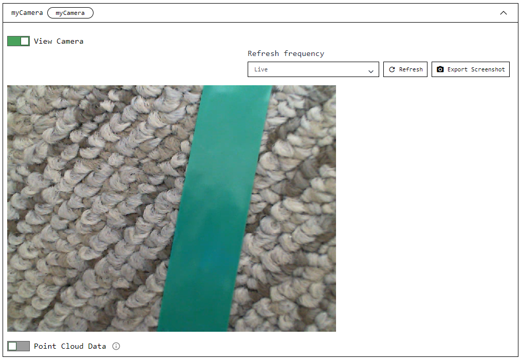
- Go to the CONTROL tab, click on the base panel, and toggle the camera to on. Ensure the camera works as expected.
- Enable the keyboard controls and move the base using your keyboard. Ensure that the base moves as expected.TIP: If one or both drive motors are going backwards, you can power down the Pi by running
sudo poweroff, unplug the battery, and switch the wires to the motor before powering it back on.<video autoplay loop muted playsinline alt="Driving the base from the control tab." width=100% style=width:600px class=aligncenter><source data-src=./assets/lf-viamapp-base-view5.webm type=video/webm><source data-src=./assets/lf-viamapp-base-view5.mp4 type=video/mp4>There should have been a video here but your browser does not seem to support it.</video>
You'll use the vision service color detector to programmatically identify the line to follow. Before you can start on that, you need to get creative though and use your colored tape to make a path for your robot to follow. Perhaps a circle or other shape, or perhaps a path from one point of interest to another. Sharp corners will be more challenging for the robot to follow so consider creating more gentle curves.
Once you have created your path, set your robot on the line such that the line appears in the front of the camera's view. Verify that the camera sees the line by viewing the camera feed on the CONTROL tab of the machine page.
Now, let's configure the color detector so your rover can detect the line:
Next, navigate to the CONFIGURE tab of your machine's page.
- Add a vision service.Next, add a vision service detector:Click the + (Create) icon next to your machine part in the left-hand menu and select Component or service. Select type
visionand modelcolor detector. Entergreen_detectorfor the name, then click Create.In your vision service's panel, select the color your vision service will be detecting, as well as a hue tolerance and a segment size (in pixels). Use a color picker like colorpicker.me to approximate the color of your line and get the corresponding rgb or hex value. We usedrgb(25,255,217)or#19FFD9to match the color of our green electrical tape, and specified a segment size of 100 pixels with a tolerance of 0.06, but you can tweak these later to fine tune your line follower. - Click Save in the top right corner of the screen.
- (optional) Add a
transformcamera as a visualizerIf you'd like to see the bounding boxes that the color detector identifies in a live stream, you'll need to configure a transform camera. This isn't another piece of hardware, but rather a virtual "camera" that takes in the stream from the webcam we just configured and outputs a stream overlaid with bounding boxes representing the color detections.Click the + (Create) icon next to your machine part in the left-hand menu and select Component or service. Add a transform camera with typecameraand modeltransform. Name ittransform_camand click Create.Click {} (Switch to advanced) in the top right of the camera's configuration panel to switch to advanced mode. Replace the attributes JSON object ({}) with the following object which specifies the camera source that thetransformcamera will be using and defines a pipeline that adds the defineddetector:{ "source": "my_camera", "pipeline": [ { "type": "detections", "attributes": { "detector_name": "green_detector", "confidence_threshold": 0.6 } } ] } - Click Save in the top right corner of the screen.
Navigate to your machine's CONTROL tab to test the transform camera. Click on the transform camera panel and toggle the camera on. You should now be able to view the camera feed with color detector overlays superimposed on the image.
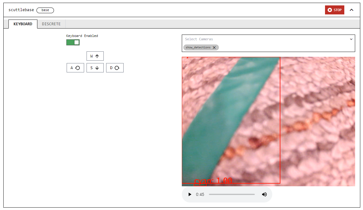
If the camera feed does not render color detector overlays on top of the colored tape, adjust the color hex code and the hue tolerance in the Vision service configuration until it is able to do so successfully.
To make your rover follow your line, you need to install Python and the Viam Python SDK and then write the logic that handles navigation along the line:
Requirements
- Make sure you have Python installed. You can double-check this by running:
orpython --versionpython3 --version - Install the Viam Python SDK by running
orpip install viam-sdkpip3 install viam-sdk
- Download the robot line follower code.
- From your robot's page, go to the CONNECT tab's Code sample page and select Python.Copy the machine's address and API key and paste them into the definition for the
connect()function, replacing the placeholders shown there.Also, add the following import to the beginning of your code:
You use these helper functions in your program to convert images captured.from viam.media.utils.pil import pil_to_viam_image, viam_to_pil_image - You can run the program from your computer or from your Pi. If you would like to get your program onto your Pi, you have a few options. If you're just trying to get this running as quickly as possible, do the following:
- In your Pi terminal, navigate to the directory where you'd like to save your code. Run, nano rgb_follower.py (or replace rgb_follower with the your desired filename).
- Paste all your code into this file. Press CTRL + X to close the file. Type Y to confirm file modification, then press enter to finish.
- If you used different component names to the ones mentioned in the tutorial (
scuttlebase,my_camera, andgreen_detector), change the code to use your component names.
The code you are using has several functions:
is_color_in_front: Checks if the color is detected in the front center of the camera's view.async def is_color_in_front(camera, detector): """ Returns whether the appropriate path color is detected in front of the center of the robot. """ frame = await camera.get_image(mime_type="image/jpeg") # Convert to PIL Image pil_frame = viam_to_pil_image(frame) x, y = pil_frame.size[0], pil_frame.size[1] # Crop the image to get only the middle fifth of the top third of the # original image cropped_pil_frame = pil_frame.crop((x / 2.5, 0, x / 1.25, y / 3)) # Convert back to ViamImage cropped_frame = pil_to_viam_image(cropped_pil_frame) detections = await detector.get_detections(cropped_frame) if detections != []: return True return Falseis_color_there: Returns whether the appropriate path color is detected to the left/right of the robot's front.async def is_color_there(camera, detector, location): """ Returns whether the appropriate path color is detected to the left/right of the robot's front. """ frame = await camera.get_image(mime_type="image/jpeg") # Convert to PIL image pil_frame = viam_to_pil_image(frame) x, y = pil_frame.size[0], pil_frame.size[1] if location == "left": # Crop image to get only the left two fifths of the original image cropped_pil_frame = pil_frame.crop((0, 0, x / 2.5, y)) # Convert back to PIL Image cropped_frame = pil_to_viam_image(cropped_pil_frame) detections = await detector.get_detections(cropped_frame) elif location == "right": # Crop image to get only the right two fifths of the original image cropped_pil_frame = pil_frame.crop((x / 1.25, 0, x, y)) # Convert back to ViamImage cropped_frame = pil_to_viam_image(cropped_pil_frame) detections = await detector.get_detections(cropped_frame) if detections != []: return True return Falsestop_robot: Stops the robot's motion.async def stop_robot(machine): """ Stop the robot's motion. """ base = Base.from_robot(machine, "scuttlebase") await base.stop()
The main function connects to the robot and initializes each component, then performs the following tasks:
- If the color of the line is detected in the top center of the camera frame, the rover drives forward.
- If the color is not detected in the top center, it checks the left side of the camera frame for the color. If it detects the color on the left, the robot turns left. If it doesn't detect the color on the left, it checks the right side of the camera frame, and turns right if it detects the color.
- Once the line is back in the center front of the camera frame, the rover continues forward.
- When the rover no longer sees any of the line color anywhere in the front portion of the camera frame, it stops and the program ends.
async def main():
    """
    Main line follower function.
    """
    machine = await connect()
    print("connected")
    camera = Camera.from_robot(machine, "my_camera")
    base = Base.from_robot(machine, "scuttlebase")

    # Put your detector name in place of "green_detector"
    green_detector = VisionClient.from_robot(machine, "green_detector")

    # counter to increase robustness
    counter = 0

    # Speed parameters to experiment with
    linear_power = 0.35
    angular_power = 0.3

    # The main control loop
    while counter <= 3:
        while await is_color_in_front(camera, green_detector):
            print("going straight")
            # Moves the base slowly forward in a straight line
            await base.set_power(Vector3(y=linear_power), Vector3())
            counter == 0
        # If there is green to the left, turns the base left at a continuous,
        # slow speed
        if await is_color_there(camera, green_detector, "left"):
            print("going left")
            await base.set_power(Vector3(), Vector3(z=angular_power))
            counter == 0
        # If there is green to the right, turns the base right at a continuous,
        # slow speed
        elif await is_color_there(camera, green_detector, "right"):
            print("going right")
            await base.set_power(Vector3(), Vector3(z=-angular_power))
            counter == 0
        else:
            counter += 1

    print("The path is behind us and forward is only open wasteland.")

    await stop_robot(machine)
    await machine.close()
To run the program:
- Position the rover so that its camera can see the colored line.
- If you have saved the code on your Pi, SSH into it by running:
Replace the angle brackets and the example text with your actual Pi username and the name of your Pi. Remember to delete the angle brackets!Then, run the codessh <your_username>@<your_pi's_name>.local
The robot should continue moving along the line until it no longer sees the color of your detector except at the back of the frame, at which point it should stop moving and the code will terminate.<video autoplay loop muted playsinline alt="The green line the camera sees as the rover moves along it." width=100% style=width:300px class=aligncenter><source data-src=./assets/lf-tape-follow3.webm type=video/webm><source data-src=./assets/lf-tape-follow3.mp4 type=video/mp4>There should have been a video here but your browser does not seem to support it.</video>python3 rgb_follower.py
You now have a rover following a path of your choice, anywhere you want it to go! Along the way, you have learned how to configure a wheeled base, camera, and color detector with Viam and how to test them from the CONTROL tab.
If you are wondering what to do next, why not try one of the following ideas:
- Automatically detect what color line the robot is on and follow that.
- Use two differently colored lines that intersect and make the robot switch from one line to the other.
- Put two rovers on intersecting lines and write code to keep them from crashing into each other.
Issue: The rover moves too fast to track the line
If your rover keeps driving off the line so fast that the color detector can't keep up, you can try two things:
- Slow down the forward movement and turning speeds of the rover by decreasing the values of
linear_powerandangular_powerrespectively.- Conversely, if your rover is moving too slowly or stalling, increase the numbers (closer to
1.0which represents full power).
- Conversely, if your rover is moving too slowly or stalling, increase the numbers (closer to
- Position the camera differently, perhaps so that it is higher above the floor but still pointing downward. This will give it a wider field of view so it takes longer for the line to go out of view.
Issue: The robot is not detecting the color accurately
Things to try:
- Add a
saturation_cutoff_pctor avalue_cutoff_percentto your vision service parameters. - Try to achieve more consistent lighting on and around the line.
- Try a different color of line, or a different background. Be sure to update your
detect_colorparameter accordingly.
You can find additional assistance in the Troubleshooting section.