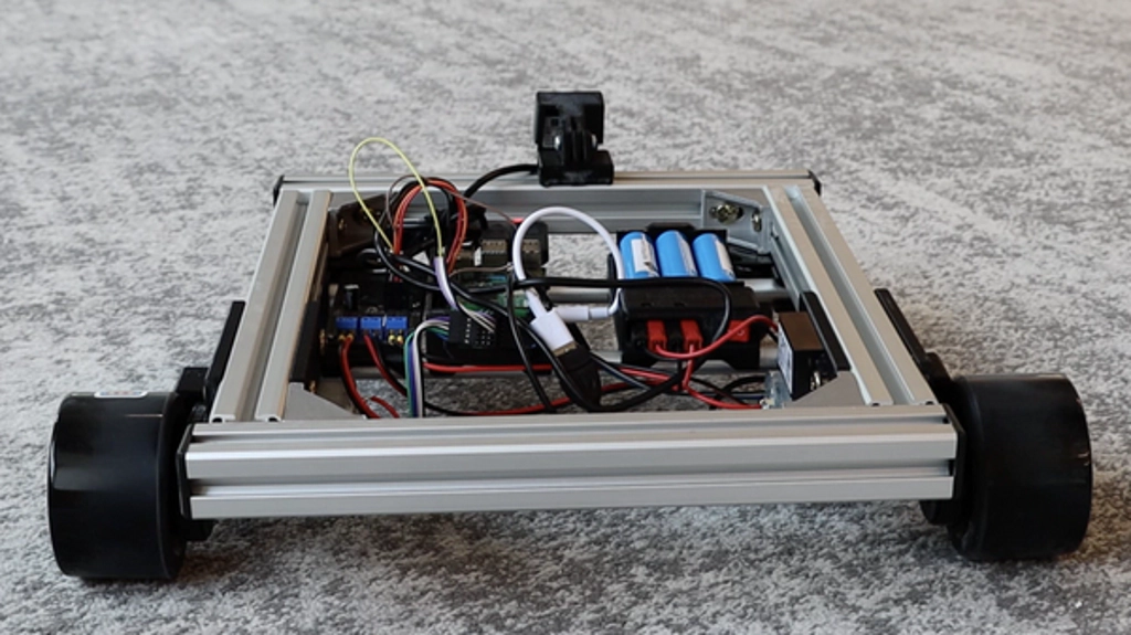
Mobile robots come in all shapes and sizes, but most kits come with a pre-defined platform that are tough to change for custom use cases. The SCUTTLE (Sensing, Connected, Utility Transport Taxi for Level Environments) is a modular, open source robotics base for building mobile robots that puts you in control with 3D printed parts, extruded aluminum, and DIN railing. When combined with Viam, you can compose hardware and software to build the smart, roving robot of your dreams.
Prerequisites
- Sign up for a free Viam account, and then sign in to the Viam app
- Hardware and supplies requirements
- 1 - Raspberry Pi 4 Model B
- 1 - microSD card to use with your Pi, at least 32GB
- 20 - jumper wires to connect the motor driver and encoders to the Pi
- 1 - Assembled SCUTTLE v3.0 Robot, includes
- robot framing kit
- cables for power, motor, and encoders
- USB wide-angle camera
- wireless gamepad controller
- power pack w/ 3S Lithium-ion batteries
- power converter for 12V to 5V USB-C
- 12V motors and high-resolution encoders
For assembly instructions, follow the SCUTTLE Assembly Guide.
What You'll Learn
- How to wire up a SCUTTLE to a Raspberry Pi
- How to configure components to control SCUTTLE hardware with Viam
- How to drive a SCUTTLE base from the Viam web application
What You'll Need
- A computer with MacOS, Windows, or Linux
What You'll Build
- A remote-controllable mobile robot that can be extended with computer vision and additional sensors
Watch the Video
Follow along with the step-by-step video.
The Raspberry Pi boots from a microSD card. You need to install Raspberry Pi OS on the microSD card that you will use with your Pi. For more details about alternative methods of setting up your Raspberry Pi, refer to the Viam docs.
Install Raspberry Pi OS
- Connect the microSD card to your computer.
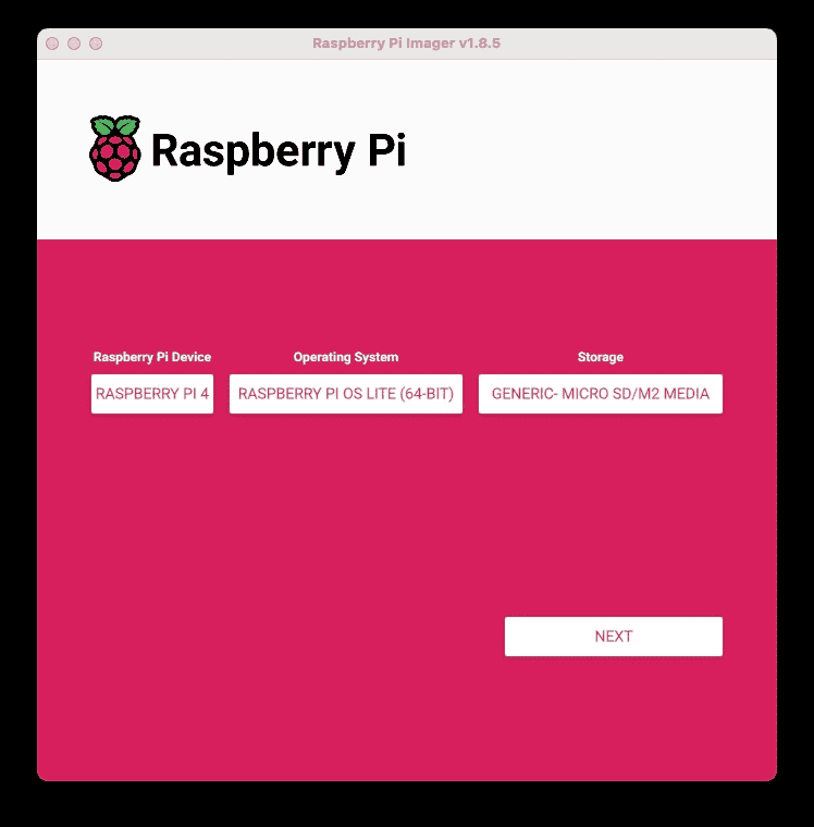
- Download the Raspberry Pi Imager and launch it.
- Click CHOOSE DEVICE. Select your Pi model, which is Raspberry Pi 4.
- Click CHOOSE OS. Select Raspberry Pi OS LITE (64-bit) from the menu.
- Click CHOOSE STORAGE. From the list of devices, select the USB flash drive you intend to use in your Raspberry Pi.
- Configure your Raspberry Pi for remote access. Click Next. When prompted to apply OS customization settings, select EDIT SETTINGS.
- Check Set hostname and enter the name you would like to access the Pi by in that field, for example,
scuttle. - Select the checkbox for Set username and password and set a username (for example, your first name) that you will use to log into the Pi. If you skip this step, the default username will be
pi(not recommended for security reasons). And specify a password. - Connect your Pi to Wi-Fi so that you can run
viam-serverwirelessly. Check Configure wireless LAN and enter your wireless network credentials. SSID (short for Service Set Identifier) is your Wi-Fi network name, and password is the network password. Change the sectionWireless LAN countryto where your router is currently being operated.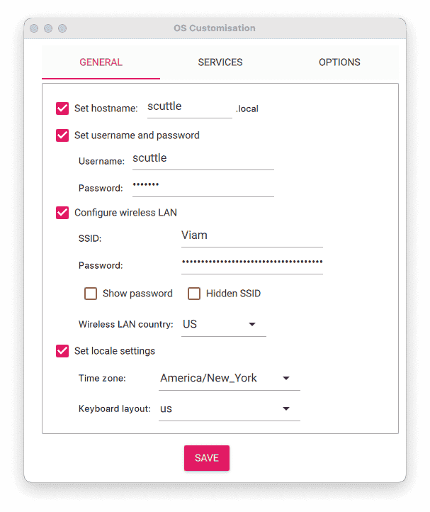
- Select the SERVICES tab, check Enable SSH, and select Use password authentication.
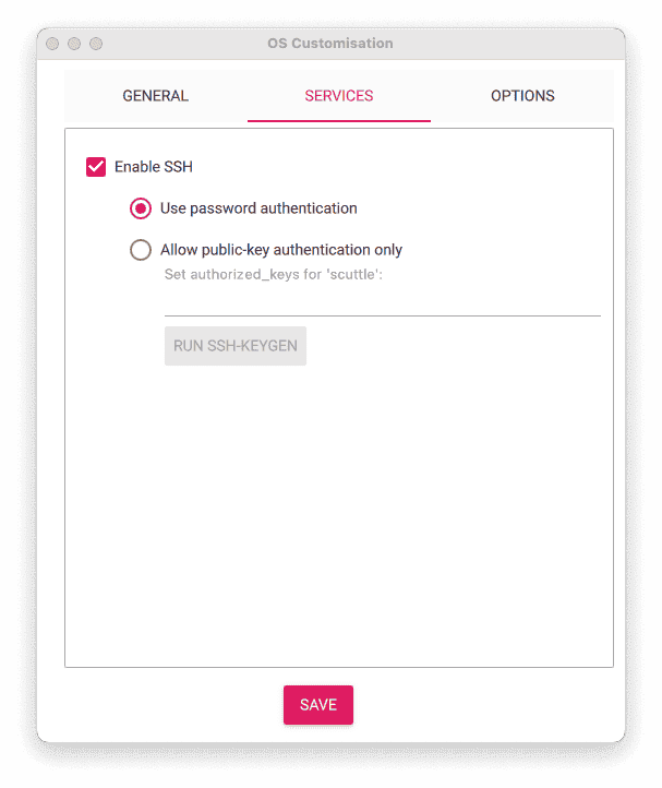
- Save your updates, and confirm
YESto apply OS customization settings. ConfirmYESto erase data on the microSD card. You may also be prompted by your operating system to enter an administrator password. After granting permissions to the Imager, it will begin writing and then verifying the Linux installation to the microSD card. - Remove the microSD card from your computer when the installation is complete.
Connect with SSH
- Place the microSD card into your Raspberry Pi and boot the Pi by plugging it into an outlet. A red LED will turn on to indicate that the Pi is connected to power.
- Once the Pi is started, connect to it with SSH. From a command line terminal window, enter the following command. The text in <> should be replaced (including the < and > symbols themselves) with the user and hostname you configured when you set up your Pi.
ssh <USERNAME>@<HOSTNAME>.local - If you are prompted "Are you sure you want to continue connecting?", type "yes" and hit enter. Then, enter the password for your username. You should be greeted by a login message and a command prompt.
- Update your Raspberry Pi to ensure all the latest packages are installed
sudo apt update
sudo apt upgrade
Enable communication protocols
- Launch the Pi configuration tool by running the following command
sudo raspi-config - Use your keyboard to select "Interface Options", and press return.
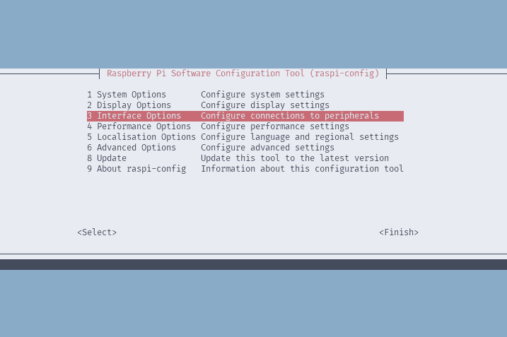
- Enable the relevant protocols to support our hardware. Since you are using encoders that communicate over I2C, enable I2C.
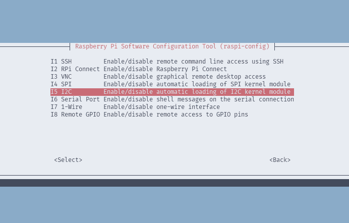
- Confirm the options to enable the I2C interface. And shut down the Pi when you're finished.
sudo shutdown -h now
The Raspberry Pi mounts to the SCUTTLE base on a custom bracket along the DIN rail between the motor driver and batteries.
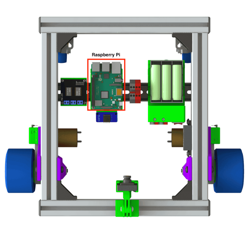
Once it has been mounted using the screws included with the SCUTTLE kit, you can wire the Raspberry Pi to the motor driver board and I2C breakout board that connects the AMS5048B encoders over a single bus.
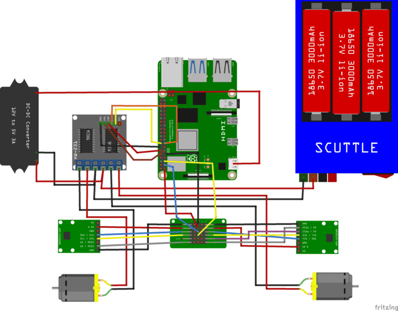
- Connect Raspberry Pi to I2C breakout (the SCUTTLE kit may include a braid of jumpers for connecting these components):
- Pin 1 (3.3v Power) to Cmps 3.3v
- Pin 3 (I2C1 SDA) to Cmps SDA
- Pin 5 (I2C1 SCL) to Cmps SCL
- Pin 9 (Ground) to Cmps GND
- Raspberry Pi to HW-231 Motor Driver (the SCUTTLE kit may include a braid of jumpers for connecting these components):
- Pin 11 (GPIO 11) to LN1
- Pin 12 (GPIO 18) to LN2
- Pin 14 (Ground) to GND
- Pin 15 (GPIO 22) to LN3
- Pin 16 (GPIO 23) to LN4
- Connect the webcam USB-A cable to any of the USB-A ports on the Raspberry Pi.
- Connect the 12v to 5v power converter USB-C cable to the USB-C power port on the Raspberry Pi.
How does the Raspberry Pi communicate with the encoders?
Create your machine in Viam
- In the Viam app under the LOCATIONS tab, create a machine by typing in a name and clicking Add machine.
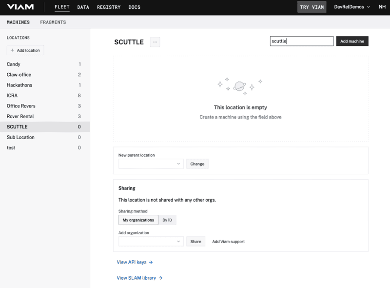
- Click View setup instructions.
- Select the
Linux / Aarch64platform for the Raspberry Pi to control the SCUTTLE, and leave your installation method asviam-agent.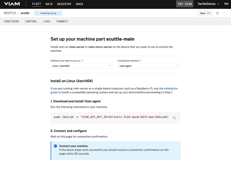
- Use the
viam-agentto download and installviam-serveron your Raspberry Pi. Follow the instructions to run the command provided in the setup instructions from the SSH prompt of your Raspberry Pi.
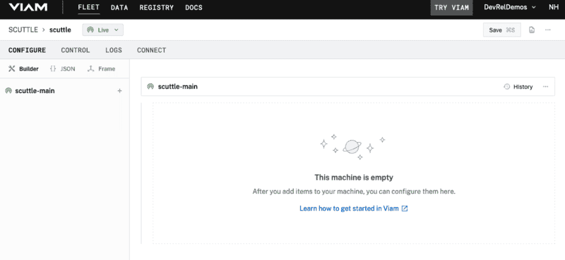
Once this process has completed, the page will indicate that the machine is connected to Viam app and Live.
Configure the board component
The board component provides access to the GPIO pins on the Raspberry Pi.
- From the Configure tab in the Viam app, click on the + icon in the left-hand menu, select Component, and search for "pi":
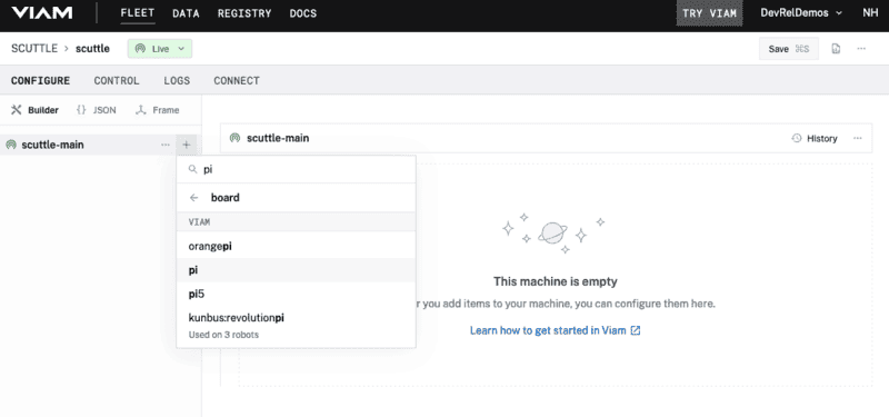
- Select the
pimodule and provide a memorable name, like "pi". Click Create.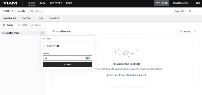
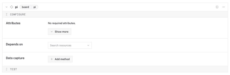
- A component card will appear on the right-hand side. It does not require any additional configuration in the card.
Configure the encoder components
The encoder component enables reading the encoder data through the I2C bus on the Raspberry Pi.
- Click the + icon, select Component, and search for "encoder".
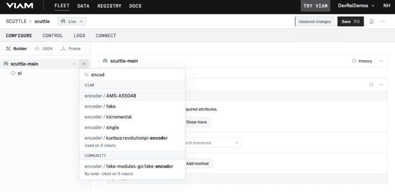
- Select the
AMS-AS5048module and provide a memorable name, like "right-encoder". Click Create. - A component card will appear on the right-hand side with the name you entered. In the Attributes field for
connection_type, enter "i2c". Then click Show more to reveal thei2c_attributesfields; enter "65" for thei2c_addrand "1" for thei2c_bus.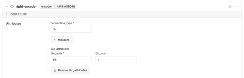
- Hover your mouse over the name of the right encoder component on the left sidebar and click on the ... to reveal an action menu. Select Duplicate to create a copy of the component for the left encoder in the configuration.
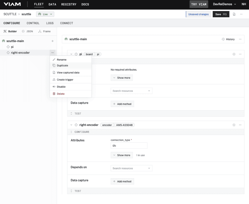
- A new component card will appear with the name of the right encoder component plus "-copy". Click on the name and rename it to something memorable, like "left-encoder".
- Click on Show more in the left encoder Attributes and update the
i2c_addrfield to "64".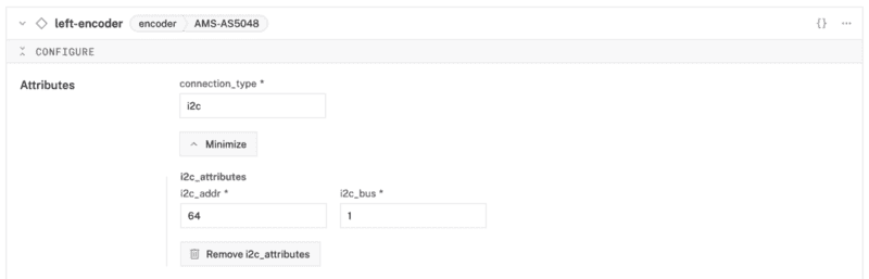
Configure the motor components
The motor component enables controlling the 12v motors through the GPIO pins on the Raspberry Pi. Each motor will be configured to work with an encoder to keep track of speed and direction when moving around.
- Click the + icon, select Component, and search for "gpio".
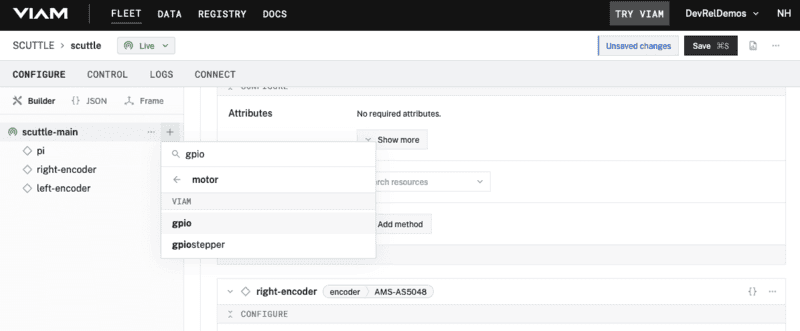
- Select the
gpiomotor module and provide a memorable name, like "right-motor". Click Create. - A component card will appear on the right-hand side with the name you entered. In the Attributes field for
board, select the name of your board component (i.e. "pi"). Click on Show more to reveal the additional fields; select "right-encoder" for theencoderdropdown and enter "2" for theticks_per_rotation. Under the Component pin assignment section, select "Ln1/Ln2" forType; enter "16" foraand "15" forb.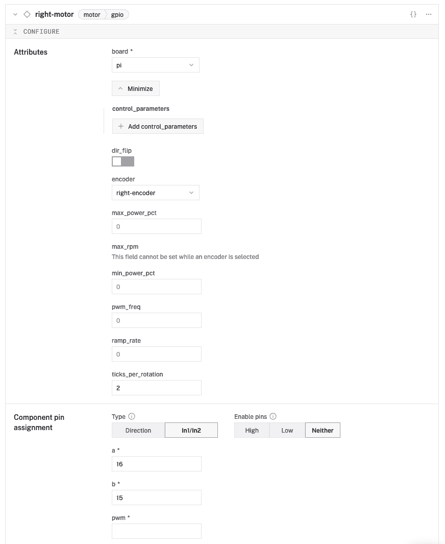
- Hover your mouse over the name of the right motor component on the left sidebar and click on the ... to reveal an action menu. Select Duplicate to create a copy of the component for the left motor in the configuration.
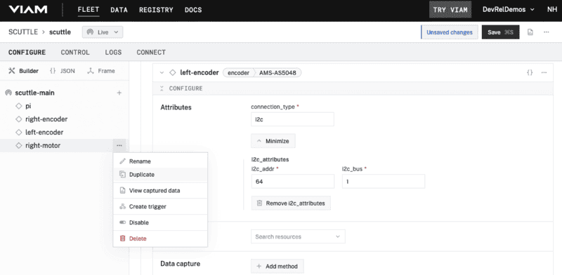
- A new component card will appear with the name of the right motor component plus "-copy". Click on the name and rename it to something memorable, like "left-motor".
- Click on Show more in the left motor Attributes and update the
encoderfield to "left-encoder". Under Component pin assignment, setato "12" andbto "11".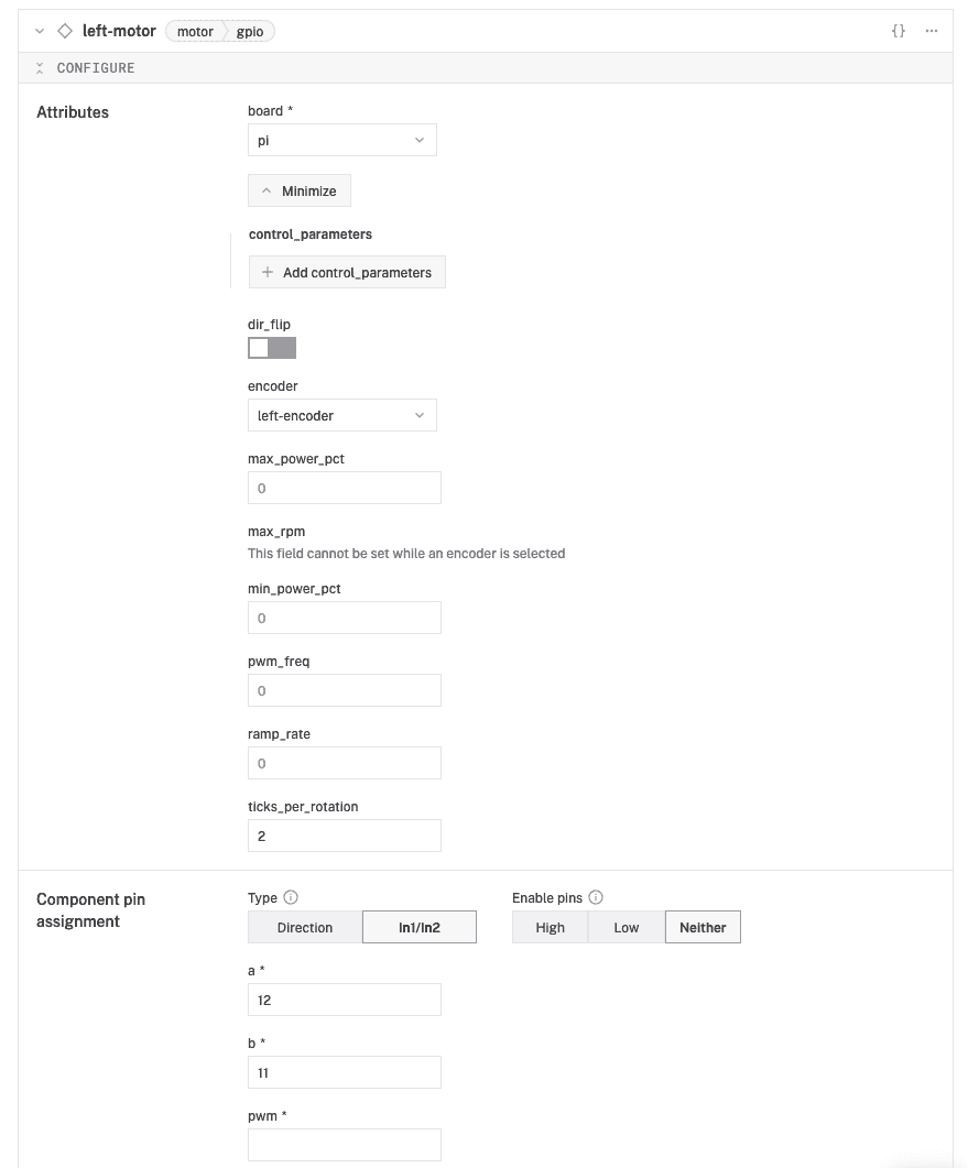
Configure the base component
The base component combines the motor components into a single entity that has built-in logic for controlling 2+ wheeled robots, for example turning a certain direction or speed.
- From the Configure tab in the Viam app, click on the + icon in the left-hand menu, select Component, and search for "wheeled":
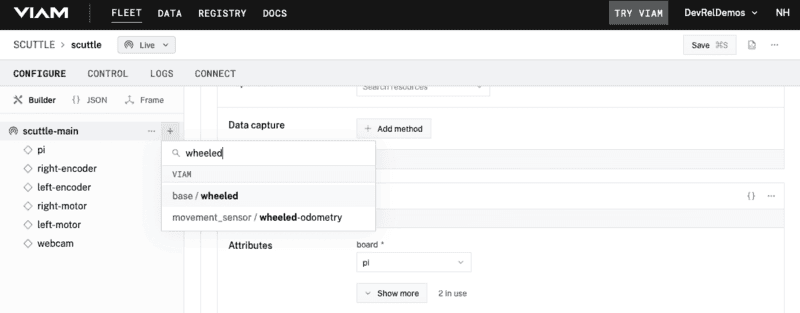
- Select the base /
wheeledmodule and provide a memorable name, like "base". Click Create. - A component card will appear on the right-hand side. In the Attributes field for
leftandright, select the appropriate motor component; in thewheel_circumference_mmfield, enter "250" and, in thewidth_mmfield, enter "400". The width is measured between the middle of each wheel in millimeters.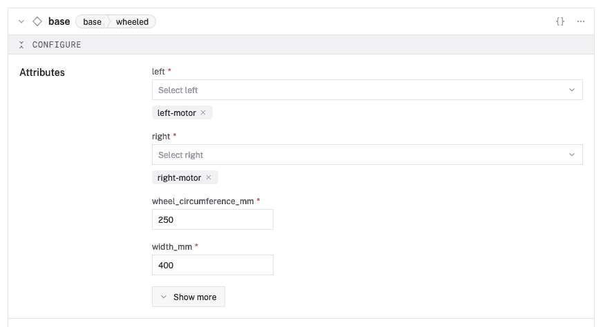
configure the camera component
Finally, the camera component provides access to the USB camera connected to the Raspberry Pi.
- From the Configure tab in the Viam app, click on the + icon in the left-hand menu, select Component, and search for "webcam":
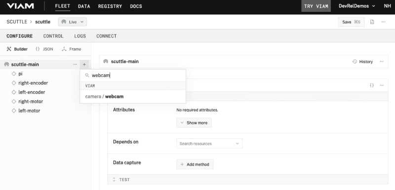
- Select the camera /
webcammodule and provide a memorable name, like "webcam". Click Create. - A component card will appear on the right-hand side. In the Attributes field for
video_path, enter "/dev/video0".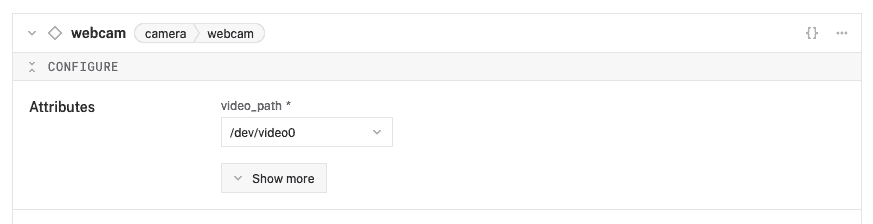
Remember to click on the Save button at the top once you've completed the configuration. Now it's time to take control of your robot!
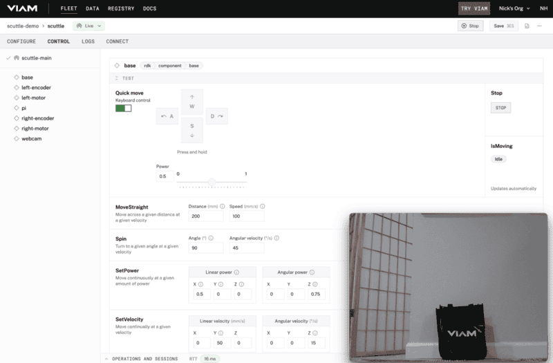
Test the base
Click on the Control tab to view the remote control cards for each of the configured components. The base controls provide several actions, including Quick move for going forwards or backwards, turning left or right by clicking on the available buttons. Toggling Keyboard control will let you use your computer keyboard's arrow keys or W,A,S,D keys to drive the SCUTTLE!
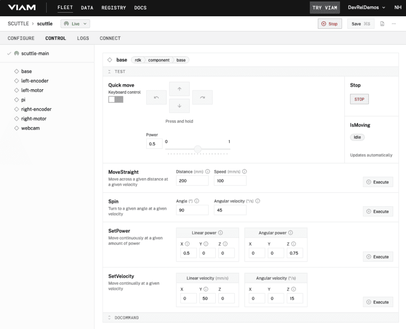
Try out some of the other actions like moving straight for a set distance and speed, or spinning around.
Test the camera
From the Control tab, click on the name of your camera component in the left sidebar to scroll to the associated control card. Activate the View toggle to see a live feed of what your SCUTTLE sees!
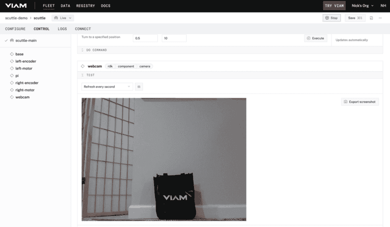
Hovering over the camera stream or to the right-hand side of it, click on the picture-in-picture button to keep the camera stream in view while driving the base from its control card.
Congrats, you have the foundation for a tele-operated or autonomous mobile smart machine using Viam and SCUTTLE! 🎉
Make your SCUTTLE smarter
With this foundation in place, you can add more components and services to build the robot of your dreams.
- Modify the design: Check out the additional models from SCUTTLE for adding sensors or changing the shape of your robot with a body cover, a lidar mount, or different sized wheels.
- Update the controls: The SCUTTLE kit includes a wireless gamepad. Try adding that as an input controller to drive the base away from your computer.
- Make it autonomous: Add a pre-trained computer vision model to enable following a specific color or recognize objects while navigating around in a pattern.
Check out our documentation for more inspiration.
What You Learned
- How to wire up a SCUTTLE to a Raspberry Pi
- How to configure components to control SCUTTLE hardware with Viam
- How to drive a SCUTTLE base from the Viam web application
Related Resources
- VIDEO
- Tipsy: Create an autonomous drink-carrying robot tutorial