Proximity alerts can be very useful, whether you're backing into a parking spot (and don't have a rearview camera), want to warn others that you're in a blind corner, or want to avoid getting too close to things. In this codelab, you'll build your own visual proximity alert that uses an RGB LED to indicate safe and dangerous distances and an ultrasonic sensor to determine those distances.
What You'll Build
- A visual proximity alert. A light will turn red (when an object is within the "danger" distance threshold) or green (when an object is within the "safe" distance threshold) based on the ultrasonic sensor.

Prerequisites
- A computer with MacOS, Windows, or Linux to flash your Raspberry Pi and configure the device's components using the Viam app.
- Hardware and supplies requirements
- 1 - Raspberry Pi 4 (recommend at least 4 GB RAM)
- 1 - microSD card to use with your Pi
- 1 - power supply for your Pi
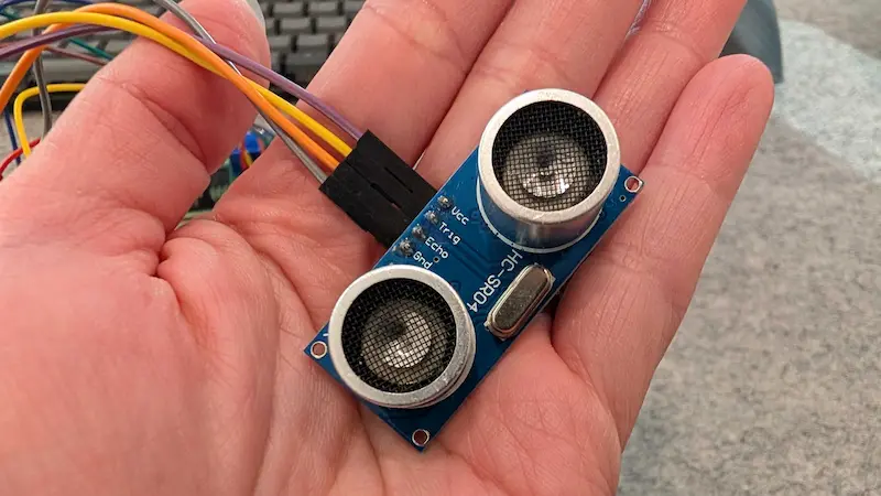
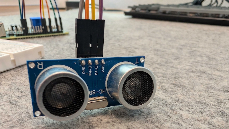
- 1 - ultrasonic sensor (I used this model)
- 1 - common cathode RGB LED
- 1 - solderless breadboard
- 1 - Resistor pack
- You'll use 2 resistors for the ultrasonic sensor (1 - 1000 Ohm, 1 - 2000 Ohm) and 3 resistors for the RGB LED (2 - 10 Ohm, 1 - 100 Ohm)
- 12 - Female to Male Jumper Wires
- Software
- Raspberry Pi Imager (to flash your Pi)
What You'll Need
- Sign up for a free Viam account, and then sign in.
- All of the hardware components listed in the prerequisites.
What You'll Learn
- How to configure and test multiple hardware components using Viam
- How to use modules from the Viam registry
- How to control an RGB LED based on an ultrasonic sensor's input
Watch the video
See a demonstration of the visual proximity alert:
The Raspberry Pi boots from a microSD card. You need to install Raspberry Pi OS on a microSD card that you will use with your Pi. For more details about alternative methods of setting up your Raspberry Pi, refer to the Viam docs.
Install Raspberry Pi OS
- Connect the microSD card to your computer.
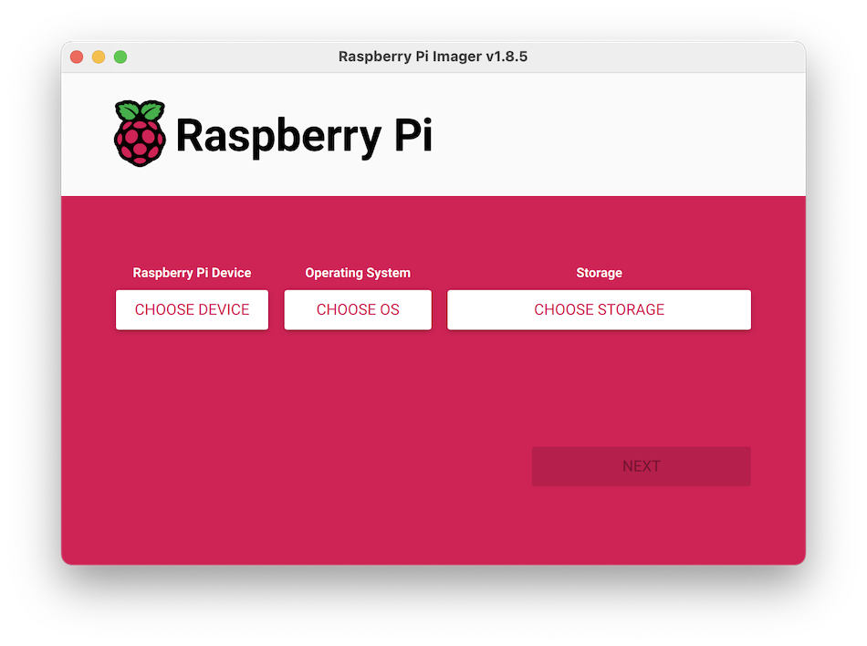
- Launch the Raspberry Pi Imager.
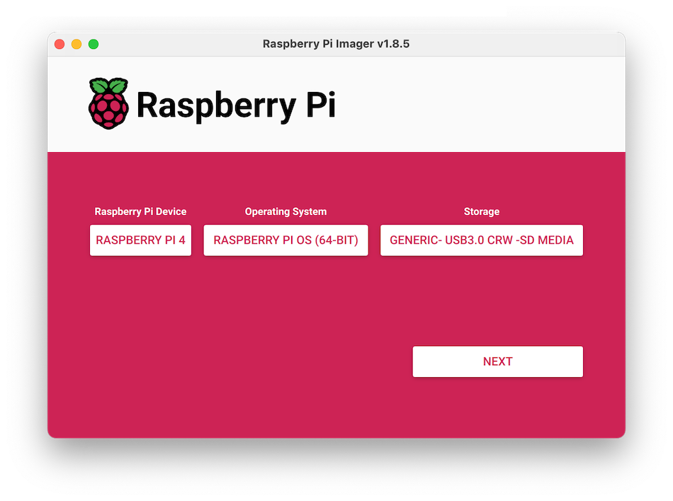
- Click CHOOSE DEVICE. Select your model of Pi, which is Raspberry Pi 4.
- Click CHOOSE OS. Select Raspberry Pi OS (64-bit) from the menu.
- Click CHOOSE STORAGE. From the list of devices, select the microSD card you intend to use in your Raspberry Pi.
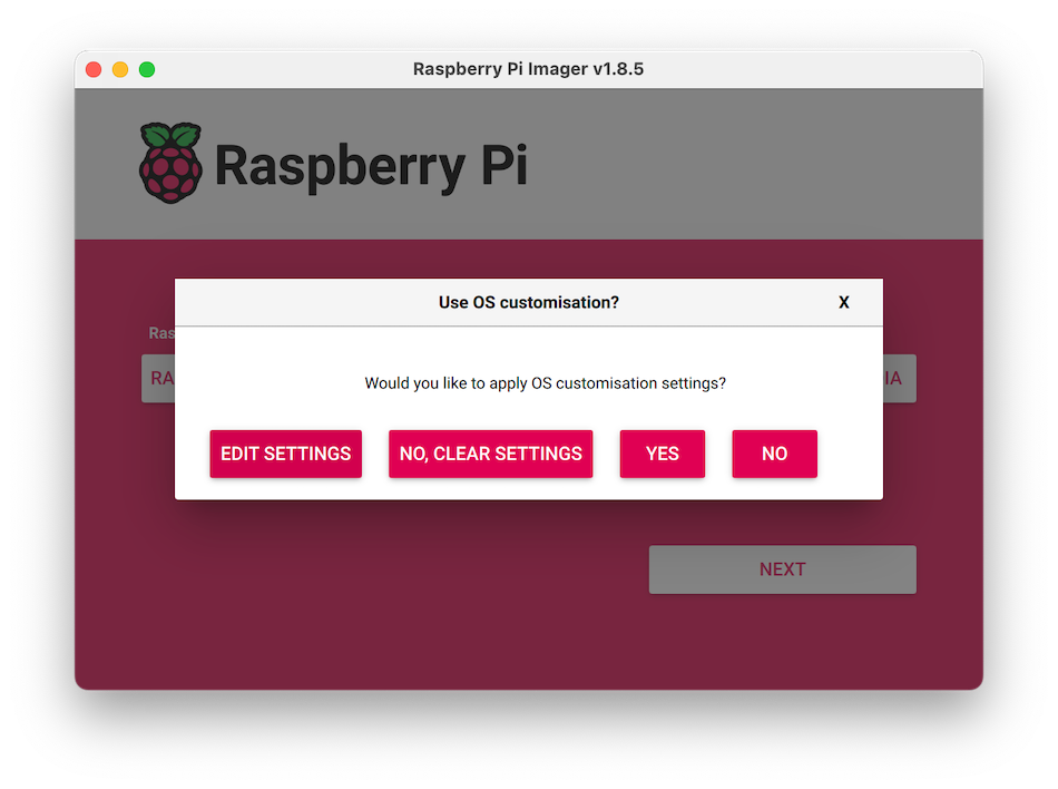
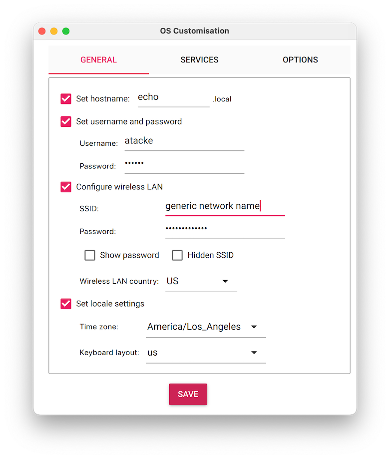
- Configure your Raspberry Pi for remote access. Click Next. When prompted to apply OS customization settings, select EDIT SETTINGS.
- Check Set hostname and enter the name you would like to access the Pi by in that field, for example,
test. - Select the checkbox for Set username and password and set a username (for example, your first name) that you will use to log into the Pi. If you skip this step, the default username will be
pi(not recommended for security reasons). And specify a password. - Check Configure wireless LAN and enter your wireless network credentials. SSID (short for Service Set Identifier) is your Wi-Fi network name, and password is the network password. Also change the section Wireless LAN country to where your router is currently being operated. This will allow your Pi to connect to your Wi-Fi so that you can run
viam-serverwirelessly. - Check Set locale settings and set your time zone and keyboard layout.
- Select the SERVICES tab, check Enable SSH, and select Use password authentication.
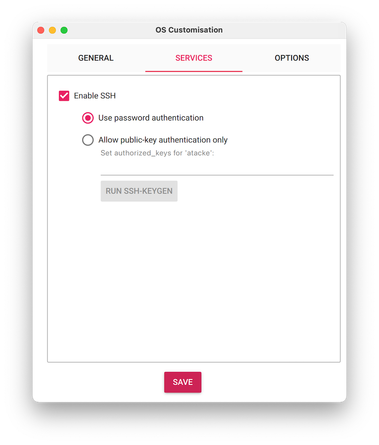
- Save your updates, and confirm
YESto apply OS customization settings. ConfirmYESto erase data on the microSD card. You may also be prompted by your operating system to enter an administrator password.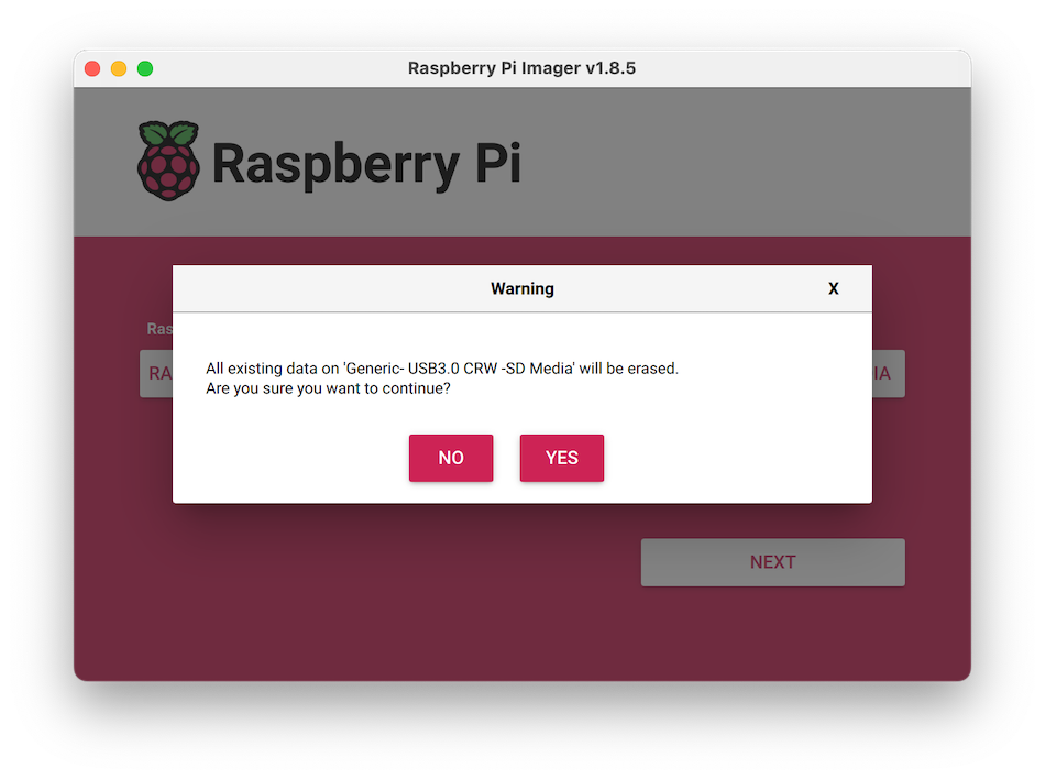 After granting permissions to the Imager, it will begin writing and then verifying the Linux installation to the microSD card.
 - Remove the microSD card from your computer when the installation is complete.
Connect with SSH
- Place the microSD card into your Raspberry Pi and boot the Pi by plugging it in to an outlet. A red LED will turn on to indicate that the Pi is connected to power.
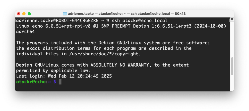
- Once the Pi is started, connect to it with SSH. From a command line terminal window, enter the following command. The text in <> should be replaced (including the < and > symbols themselves) with the username and hostname you configured when you set up your Pi.
ssh <USERNAME>@<HOSTNAME>.local # for example, my command would look like this: ssh atacke@echo.local - If you are prompted "Are you sure you want to continue connecting?", type "yes" and hit enter. Then, enter the password for your username. You should be greeted by a login message and a command prompt.
- Update your Raspberry Pi to ensure all the latest packages are installed
sudo apt update
sudo apt upgrade
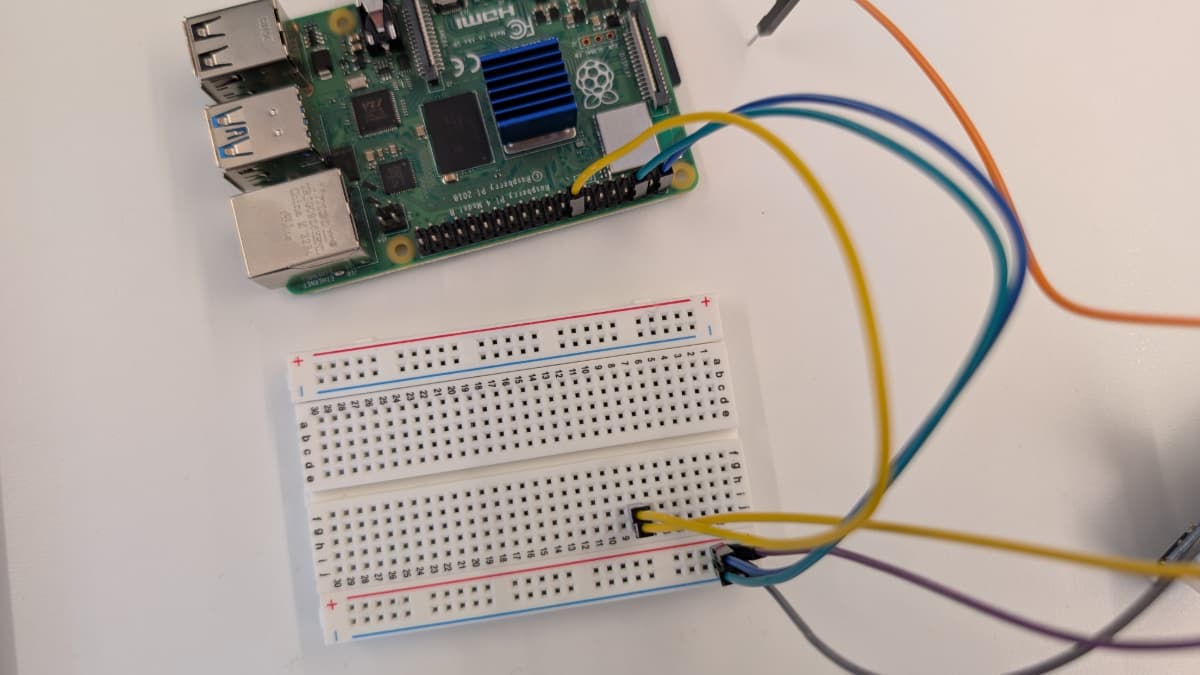
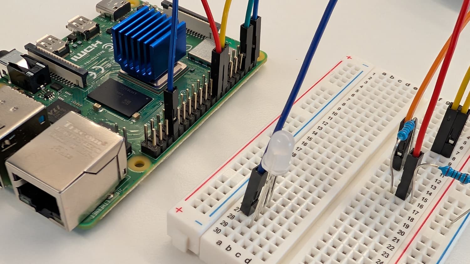
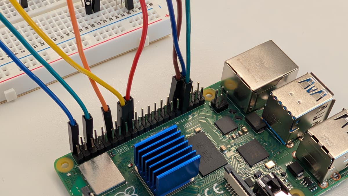
It's now time to wire our hardware components together! Here's what you'll be wiring together:

The following sections will focus on a single component at a time and show the localized wiring diagram. However, feel free to reference this full diagram when needed.
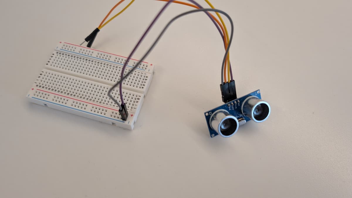
Alright, first up, the ultrasonic sensor!
First, we'll set up the ultrasonic sensor. You'll need your
- Raspberry Pi
- Ultrasonic sensor
- Breadboard
- 8 - jumper wires
- 1 - 1000 Ohm resistor
- 1 - 2000 Ohm resistor
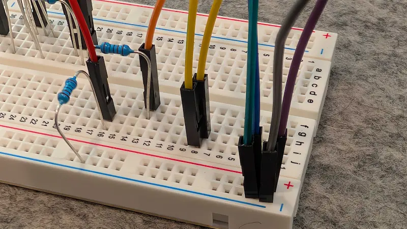
Wiring reference
- Review the wiring diagram: Refer to the following wiring diagram to see how to connect the ultrasonic sensor to the Raspberry Pi, using the breadboard and resistors to control the flow of electricity:
 The ultrasonic sensor will use 4 GPIO pins on the Raspberry Pi
Ultrasonic sensor
<->
Raspberry Pi
VCC
to
GPIO 5V (Physical Pin 2)
GND
to
GPIO GND (Physical Pin 6)
TRIG
to
GPIO 23 (Physical Pin 16)
ECHO
to
GPIO 24 (Physical Pin 18)
Step-by-step wiring instructions
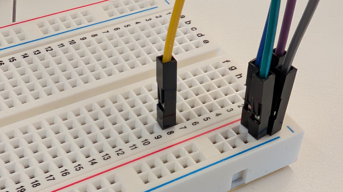
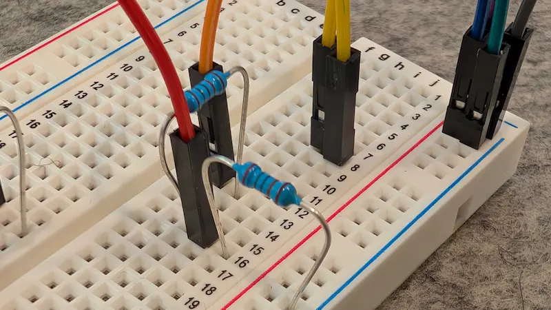
- Plug four of your jumper wires into the pins of the HC-SR04.
- Plug your VCC wire into the positive rail of your breadboard and your GND wire into the negative rail. From this point on, we'll use the breadboard to simplify the wiring process and provide a secure platform to connect components without soldering.
- Plug a jumper wire into GPIO 5V (Physical Pin 2) on your Pi and connect that wire to the positive rail of your breadboard, which connects it to VCC.
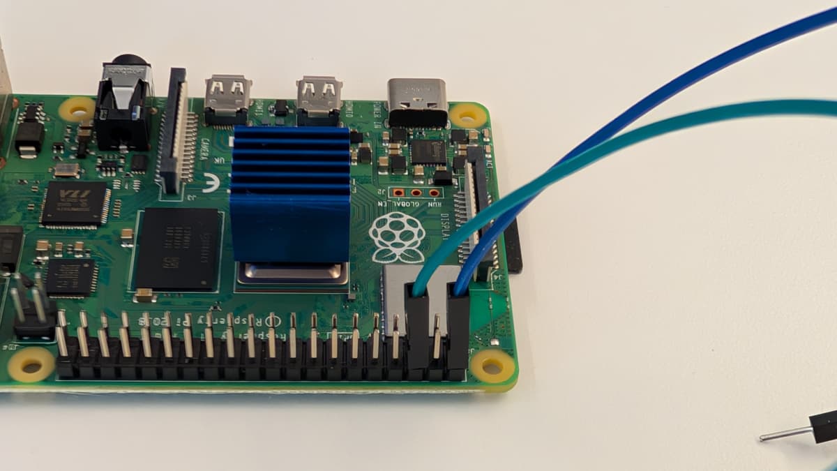
- Plug a jumper wire into GPIO GND (Physical Pin 6) on your Pi and connect that wire to the negative rail of your breadboard, which connects it to GND.
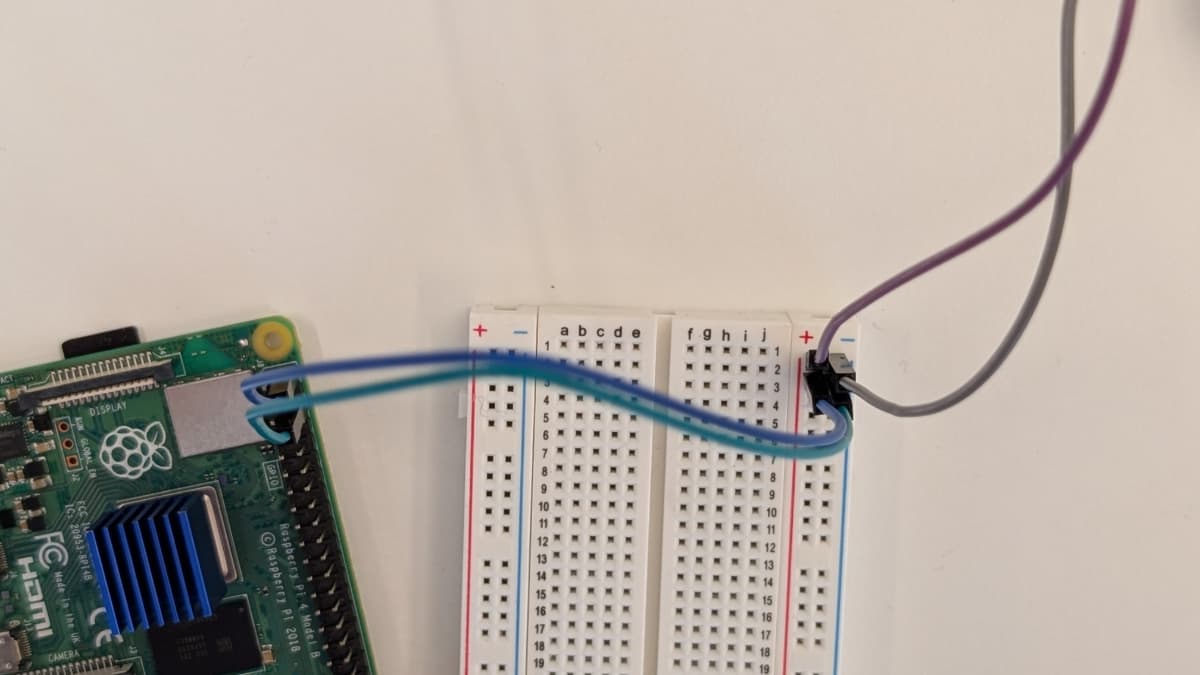
- Plug the TRIG wire from your ultrasonic sensor into a blank rail on your breadboard, then use another jumper wire to connect that rail to your Pi's GPIO 23 (Physical Pin 16) pin. (Technically, you can skip the connection on the breadboard and connect the TRIG wire directly to the Pi; it's a matter of preference!)
- Plug the ECHO wire from your ultrasonic sensor into another blank rail, then link it to another blank rail using a 1000 Ohm resistor (R1).
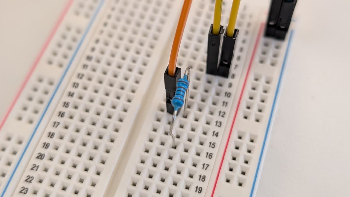
- Link your R1 rail to your GND rail using a 2000 Ohm (R2) resistor. Be sure to leave a space between the two resistors.
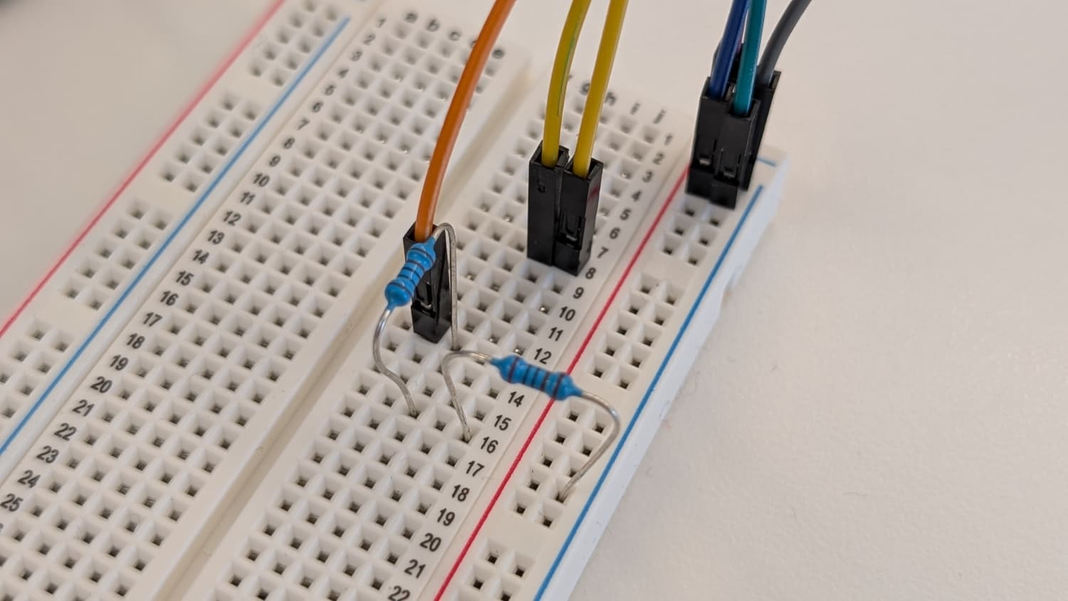
- Plug a jumper wire right where you left a space in between the resistors and connect that wire into your Pi's GPIO 24 (Physical Pin 18) pin.
Sweet! You've set up the ultrasonic sensor.
This will enable you to capture distance readings. Let's add the RGB LED next!
Next, we'll set up the RGB LED. You'll need your
- RGB LED
- 4 - jumper wires
- 2 - 10 Ohm resistors
- 1 - 100 Ohm resistor
Wiring the hardware
- Review the wiring diagram: Refer to the following wiring diagram (ultrasonic wiring omitted for clarity) to see how to connect the RGB LED to the Raspberry Pi, using the breadboard and resistors to control the flow of electricity:

The RGB LED will use 4 GPIO pins on the Raspberry PiRGB LED
<->
Raspberry Pi
Common Cathode (GND)
to
GND (Physical Pin 34)
Red
to
GPIO 13 (Physical Pin 33)
Green
to
GPIO 12 (Physical Pin 32)
Blue
to
GPIO 18 (Physical Pin 12)
Step-by-step wiring instructions
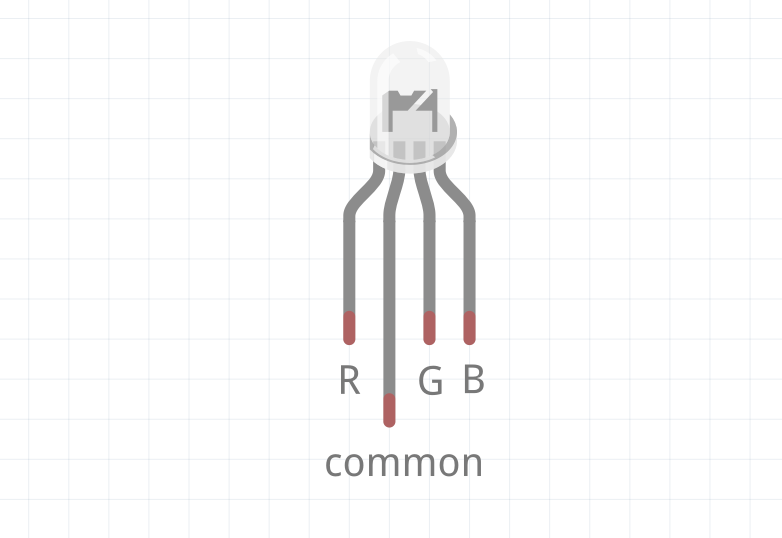
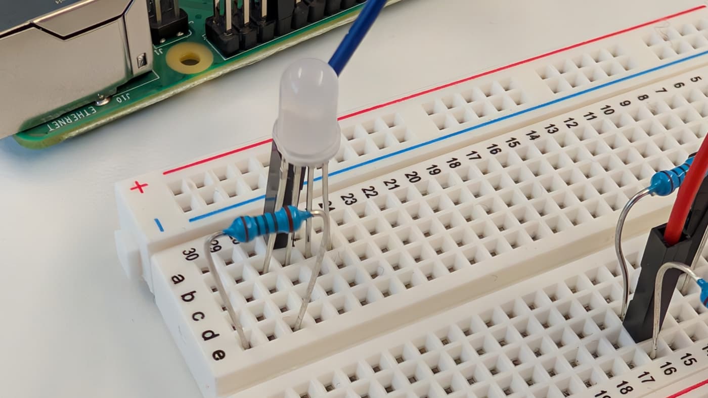
- Review the LED's orientation: A common cathode RGB LED has four legs:
- Common Cathode (GND): The longest leg, which should be connected to ground.
- Red (R): Typically the leg next to the common cathode (to the left as shown below).
- Green (G): The leg on the other side of the cathode (to the right as shown below).
- Blue (B): The farthest leg from the cathode.
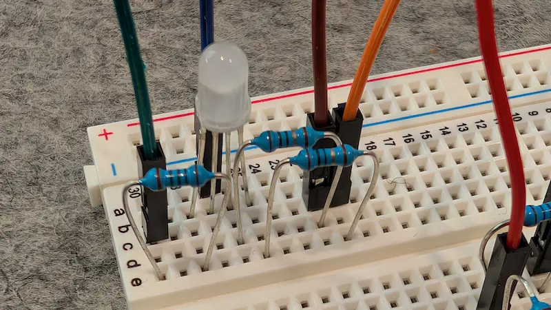
- Plug your RGB LED into a blank rail on your breadboard. From here, you'll use jumper wires and resistors to connect it to your Pi.
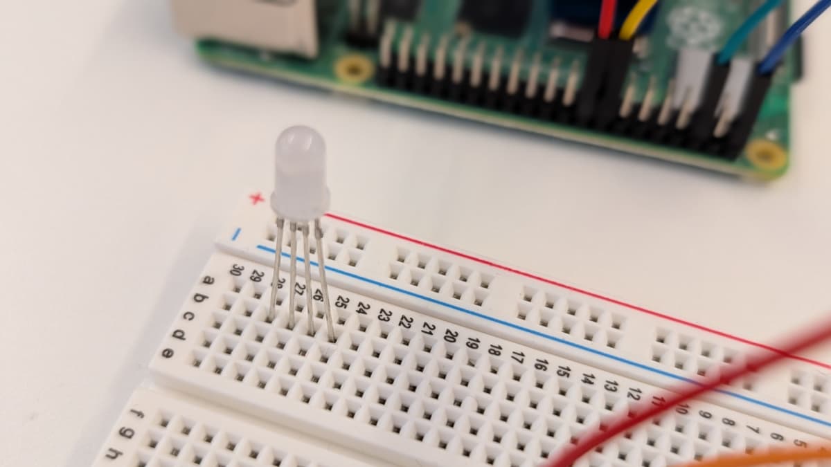
- Plug a jumper wire next to the longest leg of the LED, then connect that wire to the Pi's GND pin (Physical Pin 34). This will be your ground.
- Link a 100 Ohm resistor to the red leg of the LED.
- Link a 10 Ohm resistor to the green leg and another 10 Ohm resistor to the blue leg of the LED.
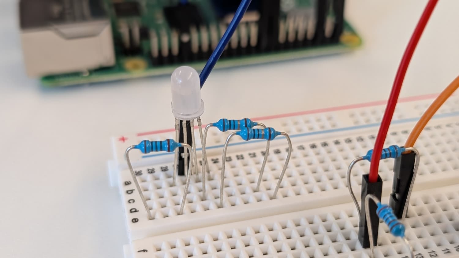
- Connect the resistors to the Pi.
- Connect a jumper wire from the red leg (100 Ohm resistor) to the Pi's GPIO 13 pin (Physical Pin 33)
- Connect a jumper wire from the green leg (10 Ohm resistor) to the Pi's GPIO 12 pin (Physical Pin 32)
- Connect a jumper wire from the blue leg (10 Ohm resistor) to the Pi's GPIO 18 pin (Physical Pin 12)
- Double-check connections to ensure correct polaity and avoid miswiring.
With the hardware all wired up, it's time to configure them within the Viam app, which we'll do in the next section.
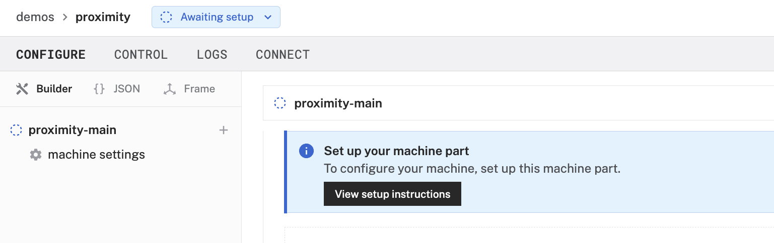
- In the Viam app under the LOCATIONS tab, create a machine by typing in a name and clicking Add machine.
- Click View setup instructions.
- To install
viam-serveron your Raspberry Pi (so you can communicate with and control your sensor and the RGB LED), select theLinux / Aarch64platform for the Raspberry Pi, and leave your installation method asviam-agent.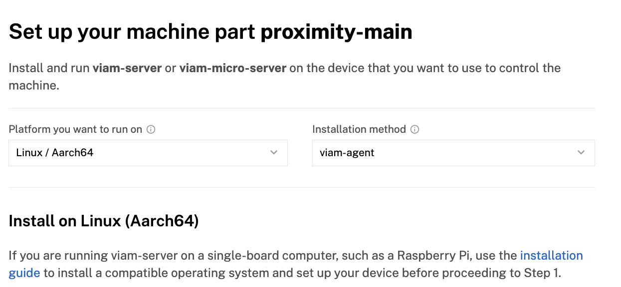
- Use the
viam-agentto download and installviam-serveron your Raspberry Pi. Follow the instructions to run the command provided in the setup instructions from the SSH prompt of your Raspberry Pi.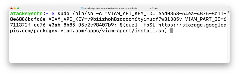
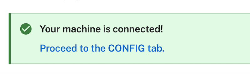
- The setup page will indicate when the machine is successfully connected.
With a machine configured and connected, it's time to add the peripherals. First, the board (AKA your Raspberry Pi).
To access the GPIO pins of your Raspberry Pi, add the board to your machine in the Viam app.
- In the Viam app, find the CONFIGURE tab.
- Click the + icon in the left-hand menu and select Component.
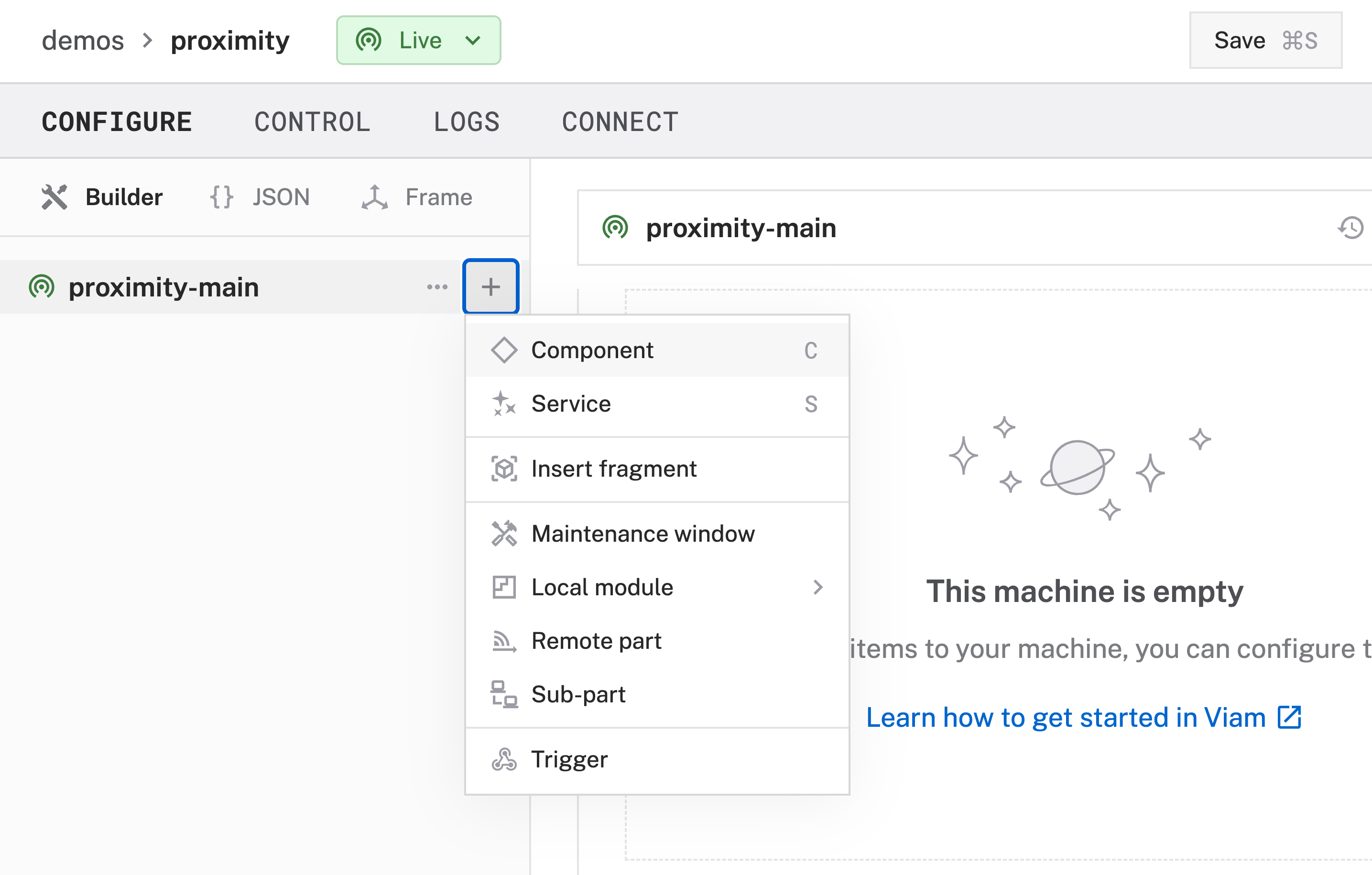
- Select
board, and find theraspberry-pi:rpi4module. Click Add Module. Leave the default nameboard-1for now, then click Create. This adds the module for working with the Raspberry Pi 4's GPIO pins.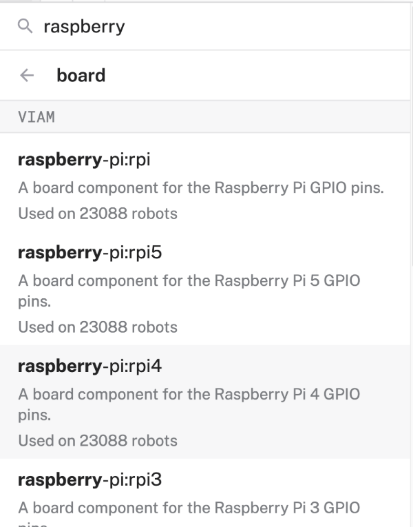
- Notice adding this module adds the board hardware component called
board-1. You'll see a collapsible card on the right, where you can configure the board component, and the correspondingboard-1part listed in the left sidebar.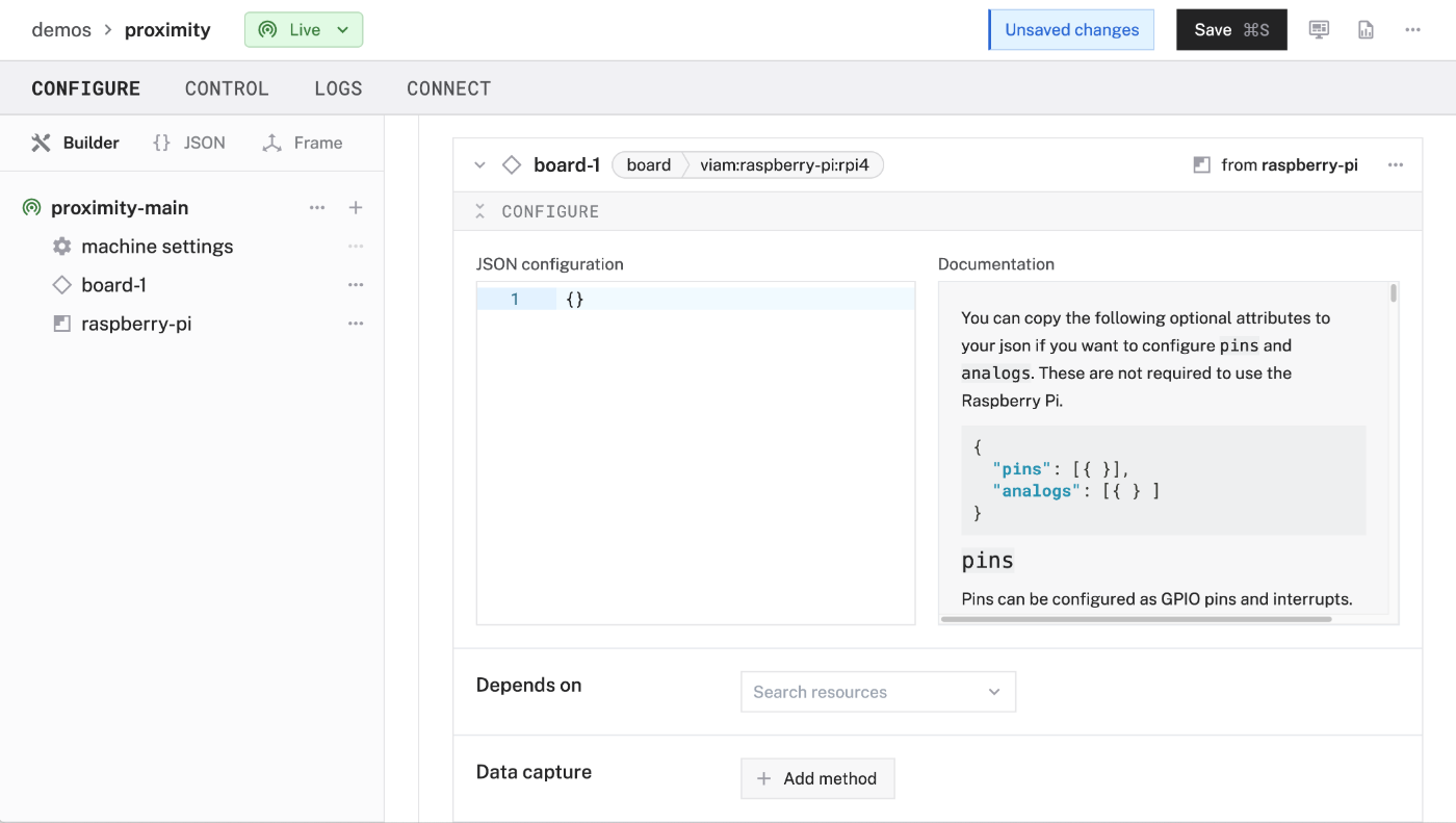
- Click Save in the top right to save and apply your configuration changes.
- Expand the TEST section of the panel to experiment with writing to physical pins. For example, since our RGB LED's red leg is connected to physical pin 33, type
33into thePinfield and set it's signal toHigh. This should turn the RGB LED on and emit a red light.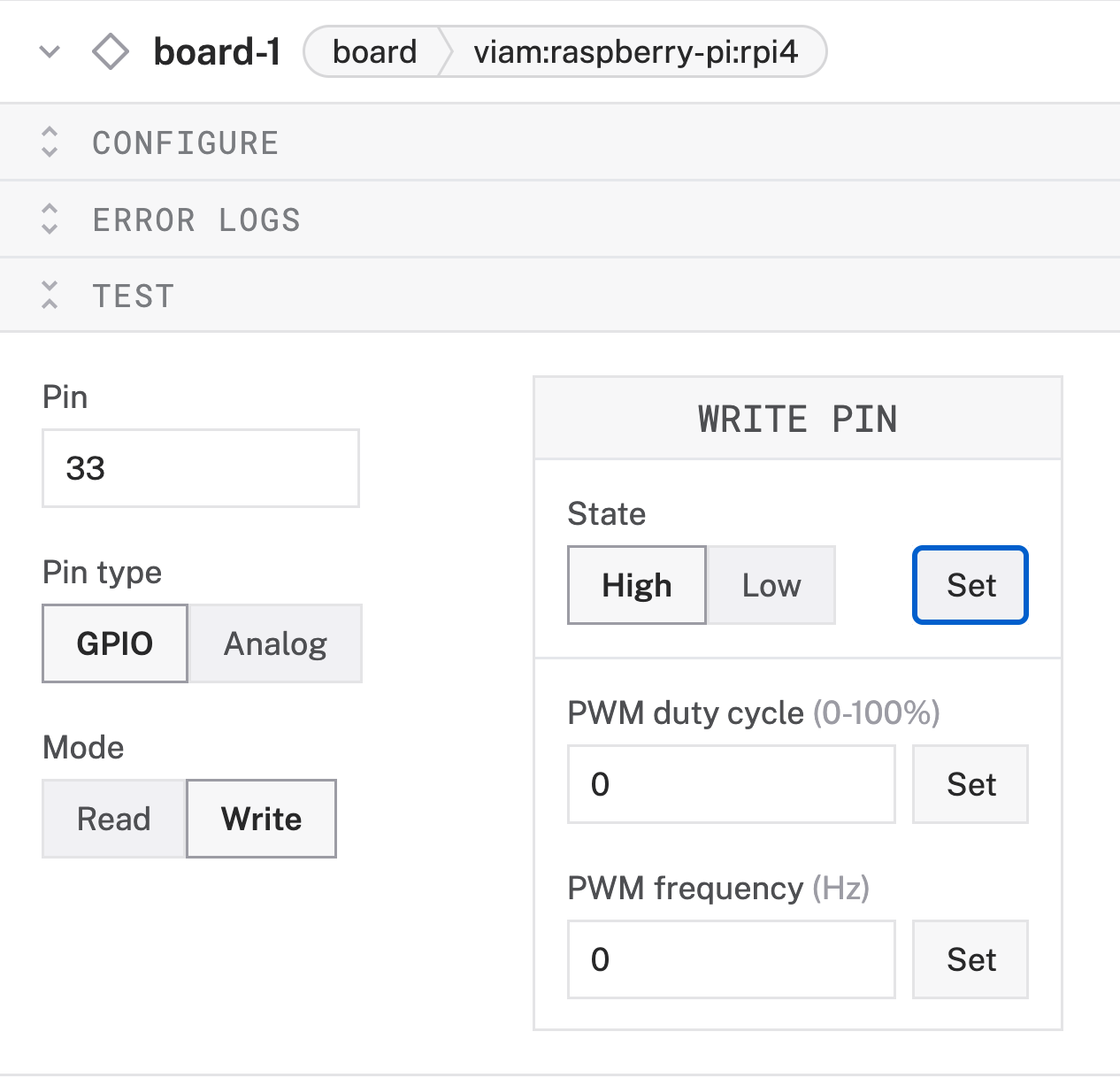
- Set the signal to
Low(for each pin previously set toHigh) to turn off the LED.
Now that your board is configured, you can configure your ultrasonic sensor next.
To access the ultrasonic sensor's measurements, add the sensor to your machine.
- In the Viam app, find the CONFIGURE tab.
- Click the + icon in the left-hand menu and select Component.
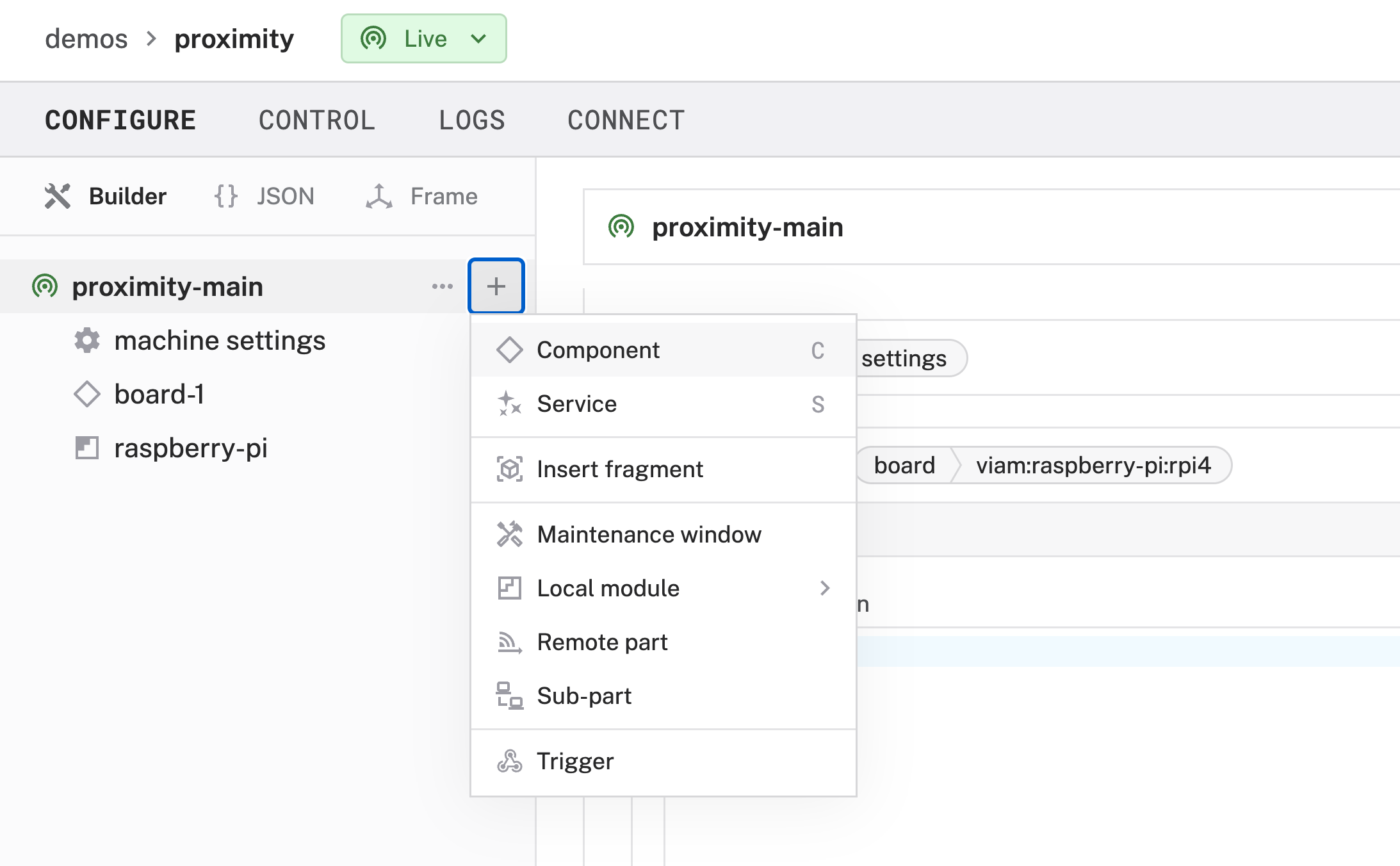
- Select
sensor, and find theultrasonic:sensormodule. Click Add Module. Leave the default namesensor-1for now, then click Create. This adds the module that gives you access to the ultrasonic sensor's readings.
- Notice adding this module adds the sensor hardware component called
sensor-1. You'll see a collapsible card on the right, where you can configure the sensor component, and the correspondingsensor-1part listed in the left sidebar.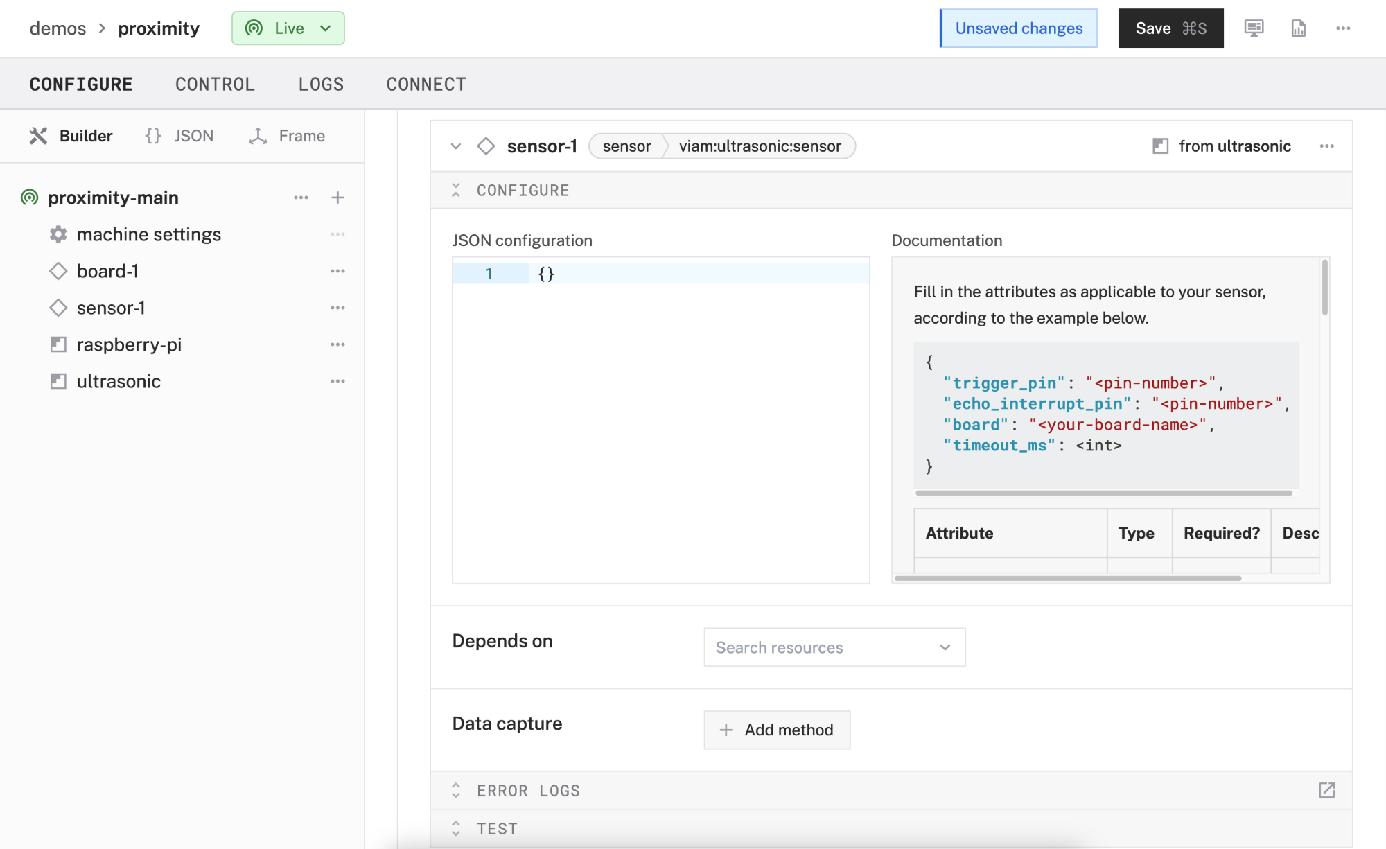
- In the JSON configuration field (within the CONFIGURE panel), add the following attributes. This tells your sensor which pins to use for its Echo Pulse Output (
ECHO) and Trigger Pulse Input (TRIG) and which board it is wired to. In your case, that'sboard-1, which is the Raspberry Pi you added earlier. You can read more about each attribute in the Documentation panel that's next to your JSON configuration{ "echo_interrupt_pin": "18", "trigger_pin": "16", "board": "board-1", "timeout_ms": 1000 // Optional; }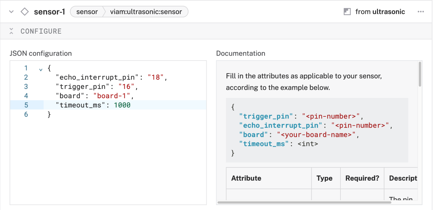
- Click Save in the top right to save and apply your configuration changes.
- Expand the TEST section of the panel to experiment with the sensor. You should see a
Get Readingslabel and a continuously updating measurement. Try placing your hand in front of the sensor and moving it farther away. The readings should reflect these changes, returning a smaller value as you place an object closer to the sensor and a larger value as you move the object farther away from the sensor.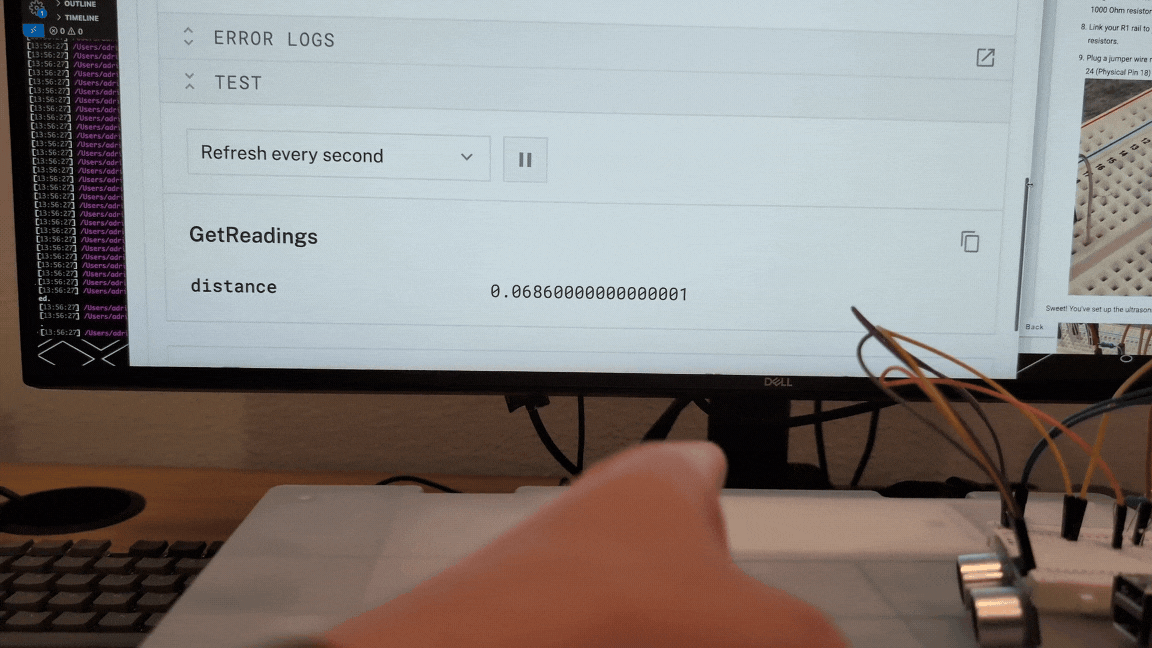
Great! You now have a working sensor and access to your board. Let's add some logic to turn the RGB LED red or green depending on the measured readings.
We can indicate when something is too close or within a safe distance (relative to the sensor) by changing the color of the RGB LED. To do this, you can write some code that processes the ultrasonic sensor's readings and sets the RGB LED to turn red or green (unsafe and safe distances, respectively). Or you can use a prebuilt module from the Viam registry that already does this for you! This step will go over how to use the proximity-alert module.
- In the Viam app, find the CONFIGURE tab.
- Click the + icon in the left-hand menu and select Service.
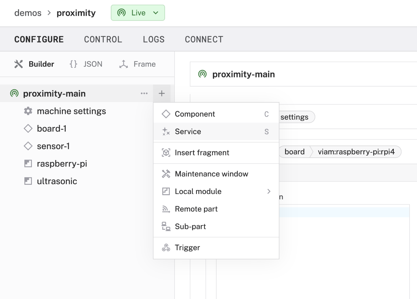
- Select
generic, and find theproximity-alert:hc-sr04_rgb-ledmodule. Click Add Module. Be sure to change the default name to something more descriptive, likeproximity-alert-service, then click Create. This adds a service that automatically turns the RGB LED red or green depending on the ultrasonic sensor's readings and a distance threshold you'll specify soon.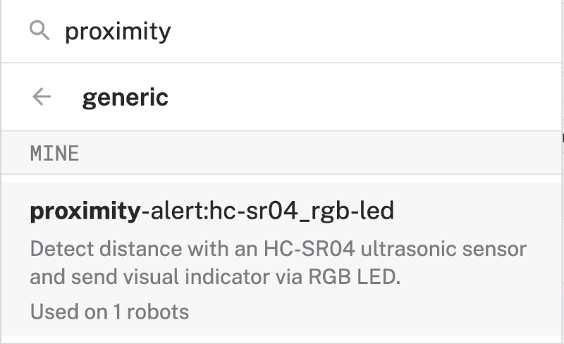
- Notice adding this module adds the generic service of your chosen name. You'll see a collapsible card on the right, where you can configure the proximity alert module, and the corresponding part listed in the left sidebar.
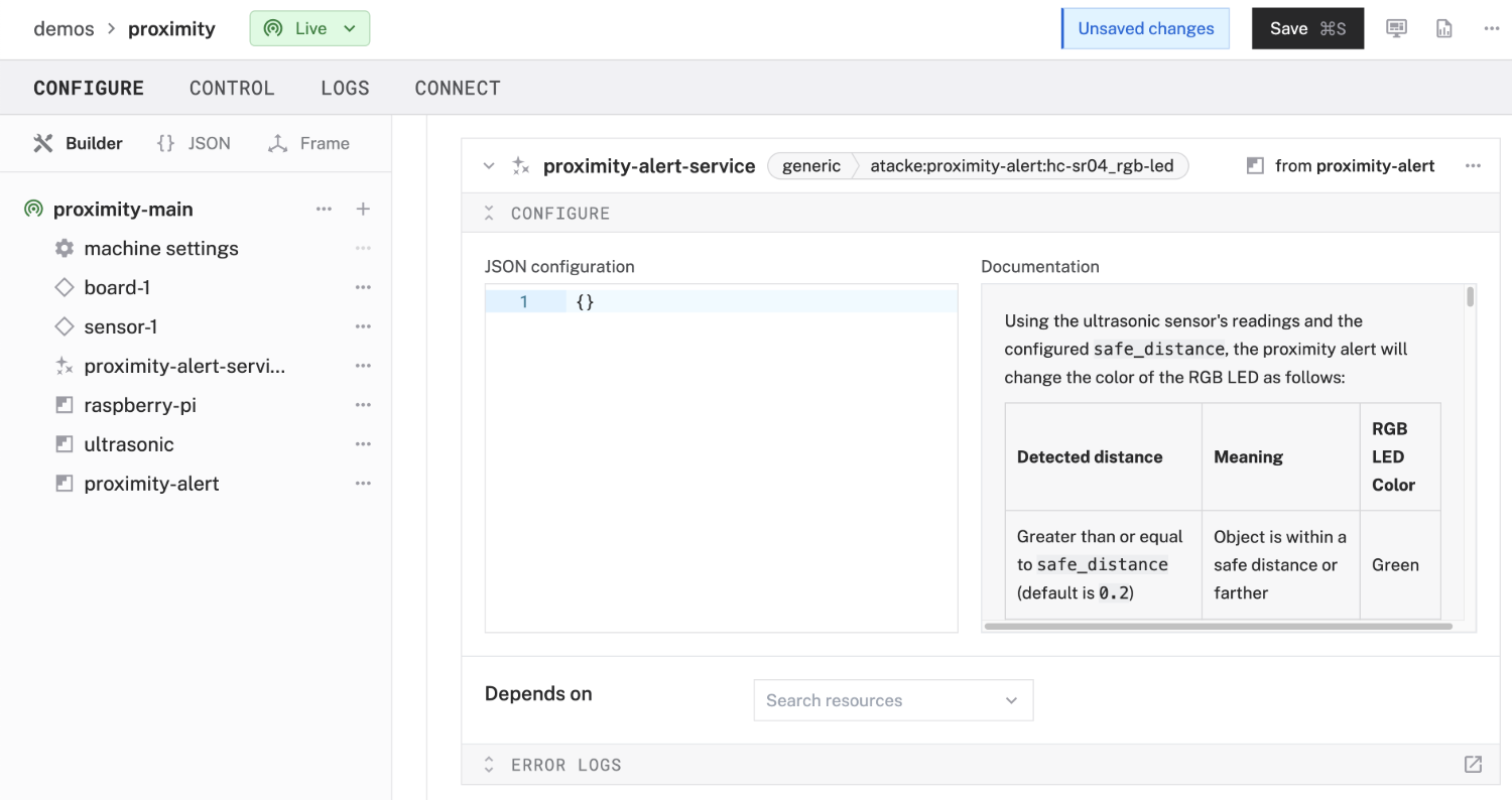
- In the CONFIGURE panel, add the following attributes (minus the comments). This tells the service which board and sensor to use (which should be the ones you've just configured), which GPIO pins to use to control the RGB LED, and a safe distance threshold to determine when to turn red or green.
// "board" and "sensor" values need to match your board and sensor component names in the Viam app
// "red_pin", "green_pin", and "blue_pin" values match GPIO pins you configured for your RGB LED
{
  "board": "board-1",
  "sensor": "sensor-1",
  "red_pin": "33",
  "green_pin": "32",
  "blue_pin": "12",
  "safe_distance": "0.3"
}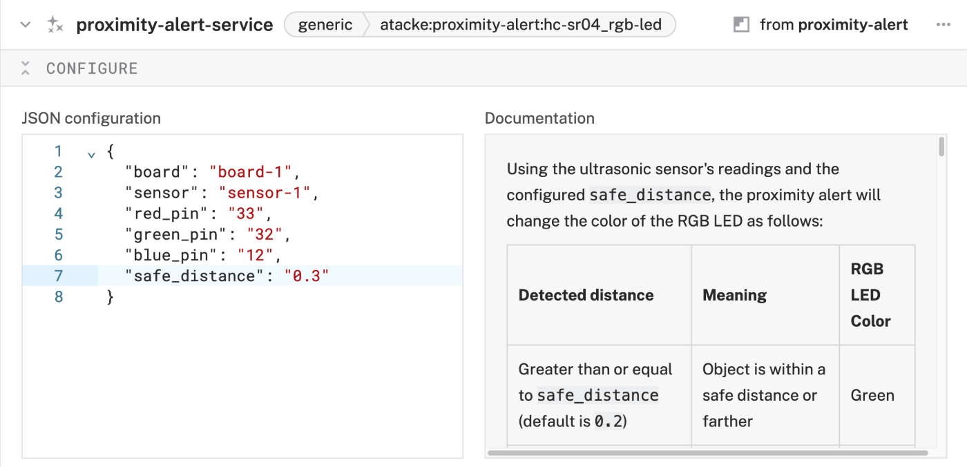
- Click Save to apply your configuration changes. This may take a moment.
- After a few moments, your RGB LED should flicker on and emit a light. Test it out! Place your hand immediately in front of the ultrasonic sensor. It should quickly emit a red light and stay red as long as you keep your hand there. When you remove your hand (and assuming there are no other objects in front of the sensor's path that is within the unsafe distance), the LED should emit a green light. To continue testing the service and ensure a bit more accuracy, position the ultrasonic sensor so that it faces some open space and that you are able to move an object within its path at variable ranges.
Congratulations! You've just built an automated proximity alert with a visual indicator! 🥳 Using some pretty common hardware components and a handy module from Viam, you created a useful device. Do let me know if you've built this!
What You Learned
- How to configure and test a device's components using Viam
- How to use modules from the Viam registry
- How to combine multiple components with a Raspberry Pi
- How to work with an ultrasonic sensor and RGB LED
Real-world applications for proximity alerts with visual indicators
This project is a great way to learn about combining different components to produce something useful; it has practical applications as well:
- Provide safety cues to those with hearing impairments or in areas where auditory alerts might be missed (due to excessive noise).
- Prevent crashes between heavy machinery and with workers on foot, with color-coded displays to indicate levels of proximity.
- Maintain safe distances from moving parts or machinery, whether on the assembly line or warehouse.
- Avoid collisons in blind spots or corners in high-traffic environments like restaurant kitchens or sports arenas.
Extend your proximity alert with Viam
Right now, you can give visual indicators based on proximity with the RGB LED. But there are other things you can do to extend your proximity alert! As an example, you could:
- Add a piezo buzzer to play a tone when something is too close.
- Send a text notification when your proximity alert detects something (or someone) gets too close to something precious (like your snacks)!